4 controls made by auma, 5 heater, 6 motor protection – AUMA Electric part-turn actuators SG 05.1 - 12.1_SGR 05.1 - 12.1 NORM User Manual
Page 11: 7 remote position transmitter, 8 limit and torque switches, 9 fitting the cover, Heater 11, Limit switches 11, Motor protection 11, Ptc thermistors 11
7.4
Controls made by AUMA
In case the required reversing contactors are not to be installed in the control
cabinet, the controls AUMA MATIC or AUMATIC can easily be mounted to the
actuator at a later date.
For enquiries and more information, please state our commission no.
(refer to actuator name plate).
7.5
Heater
AUMA part-turn actuators have a heater installed as standard. To prevent
condensation, the heater must be connected.
7.6
Motor protection
In order to protect against overheating and extreme high temperatures at the
actuator, PTC thermistors or thermoswitches are embedded in the motor
winding. The thermoswitch is tripped as soon as the max. permissible winding
temperature has been reached.
Failure to integrate PTC thermistors or thermoswitches into the control circuit
voids the warranty for the motor.
7.7
Remote position transmitter
For the connection of remote position transmitters (potentiometer, RWG),
shielded cables must be used.
7.8
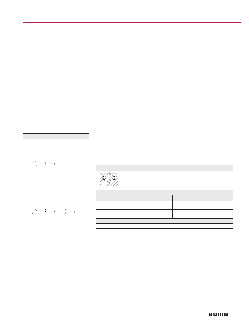
Limit and torque switches
Only the same potential can be switched on the two circuits (NC/NO contact) of
a limit or torque switch. If different potentials are to be switched simultaneously,
tandem switches are required.
To ensure correct actuator indicationss, the leading contacts of the tandem
switches must be used for that purpose and the lagging contacts for motor
switching off.
7.9
Fitting the cover
After connection:
.
Insert the socket carrier (51.0) into the plug cover (50.0) and fasten it with
screws (51.01).
.
Clean sealing faces at the plug cover and the housing.
.
Check whether O-ring is in good condition.
.
Apply a thin film of non-acidic grease (e.g. Vaseline) to the sealing faces.
.
Replace plug cover (50.0) and fasten bolts (50.01) evenly crosswise.
.
Fasten cable glands with the specified torque to ensure the required enclo-
sure protection.
Part-turn actuators SG 05.1 – SG 12.1 / SGR 05.1 – SGR 12.1
Operation instructions
AUMA NORM
11
RD
BK
RD
BK
BK
2
RD 2
BK
RD
BK
2
RD 2
BK
RD
TSC 1 / TSO 1
LSC 1 / LSO 1
TSC / TSO
LSC / LSO
DSR 1 / DÖL 1
WSR 1 / WÖL 1
DSR / DÖL
WSR / WÖL
Figure 4
I
Single switch
II
Tandem switch
SPDT
DPDT
Mechanical
life time = 2 x 10
6
starts
Type of current
Switch rating I
max
30 V
125 V
250 V
1-phase AC
(ind. load) cos phi = 0.8
5 A
5 A
5 A
DC
(resistive load)
2 A
0.5 A
0.4 A
with gold plated contacts
min. 5 V, max. 50 V
Current
min. 4 mA, max. 400 mA
Table 3: Technical data limit/torque switches
NO
NC
NC
NO