Changing the swing angle, 1 increasing the swing angle, 2 reducing the swing angle – AUMA Electric part-turn actuators SG 05.1 - 12.1_SGR 05.1 - 12.1 NORM User Manual
Page 14: Swing angle 14, Setting end stop closed, Setting limit switching open, Hanging the swing angle
10.
Changing the swing angle
The swing angle only has to be changed if the swing range for setting the end
stops (sections 8. and 9.) is not sufficient.
Unless ordered otherwise, the swing angle is set to 90°.
In the standard version, the swing angle can be adjusted within the range of 80°
to 110°.
For optional swing angle ranges, refer to Technical data, page 5.
10.1 Increasing the swing angle
.
Unscrew protective cap (16) (figure G).
.
While holding end stop nut (2.4) in position with open end wrench
(19 mm), remove set screw (2.02).
.
Turn end stop nut (2.4) counterclockwise.
Do not exceed dimension A max. (table 4).
.
Move valve manually to the desired end position OPEN.
.
Turn end stop nut (2.4) clockwise until it is tight up to the stop nut (7).
.
Degrease face of set screw (2.02).
.
Hold end stop nut in position (2.4) with open end wrench (19 mm) and fasten
set screw (2.02) with torque 85 Nm.
.
Check O-ring (016) and replace if damaged.
.
Replace protective cap (16).
10.2 Reducing the swing angle
.
Unscrew protective cap (16) (figure G).
.
While holding end stop nut (2.4) in position
with open end wrench (19 mm), remove set screw (2.02).
.
Move valve into the desired end position OPEN.
.
Turn end stop nut (2.4) clockwise until it is tight up to the stop nut (7) and do
not fall below dimension A min.
.
Degrease face of set screw (2.02).
.
Hold end stop nut in position (2.4) with open end wrench (19 mm) and fasten
set screw (2.02) with torque 85 Nm.
.
Check O-ring (016) and replace if damaged.
.
Replace protective cap (16).
14
Part-turn actuators SG 05.1 – SG 12.1 / SGR 05.1 – SGR 12.1
AUMA NORM
Operation instructions
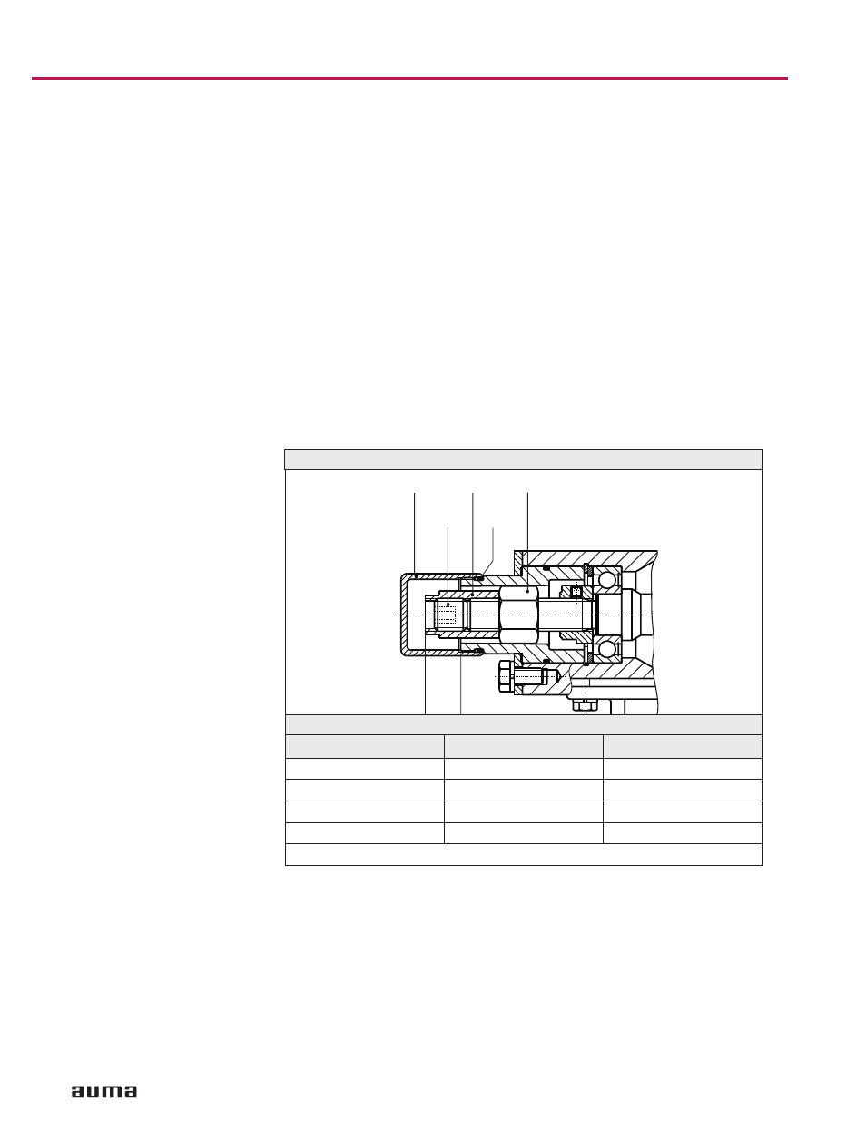
16
2.4
2.02
016
A
min.
max.
7
Figure G: Setting the swing angle
Type
A min. [mm]
A max. [mm]
SG 05.1/SGR 05.1
10
22
SG 07.1/SGR 07.1
10
22
SG 10.1/SGR 10.1
8
17
SG 12.1/SGR 12.1
12
23
Conversion factor: 1 mm corresponds to 0.0394 inch
Table 4