Caution, System protection features – atwood Levelegs System User Manual
Page 3
3
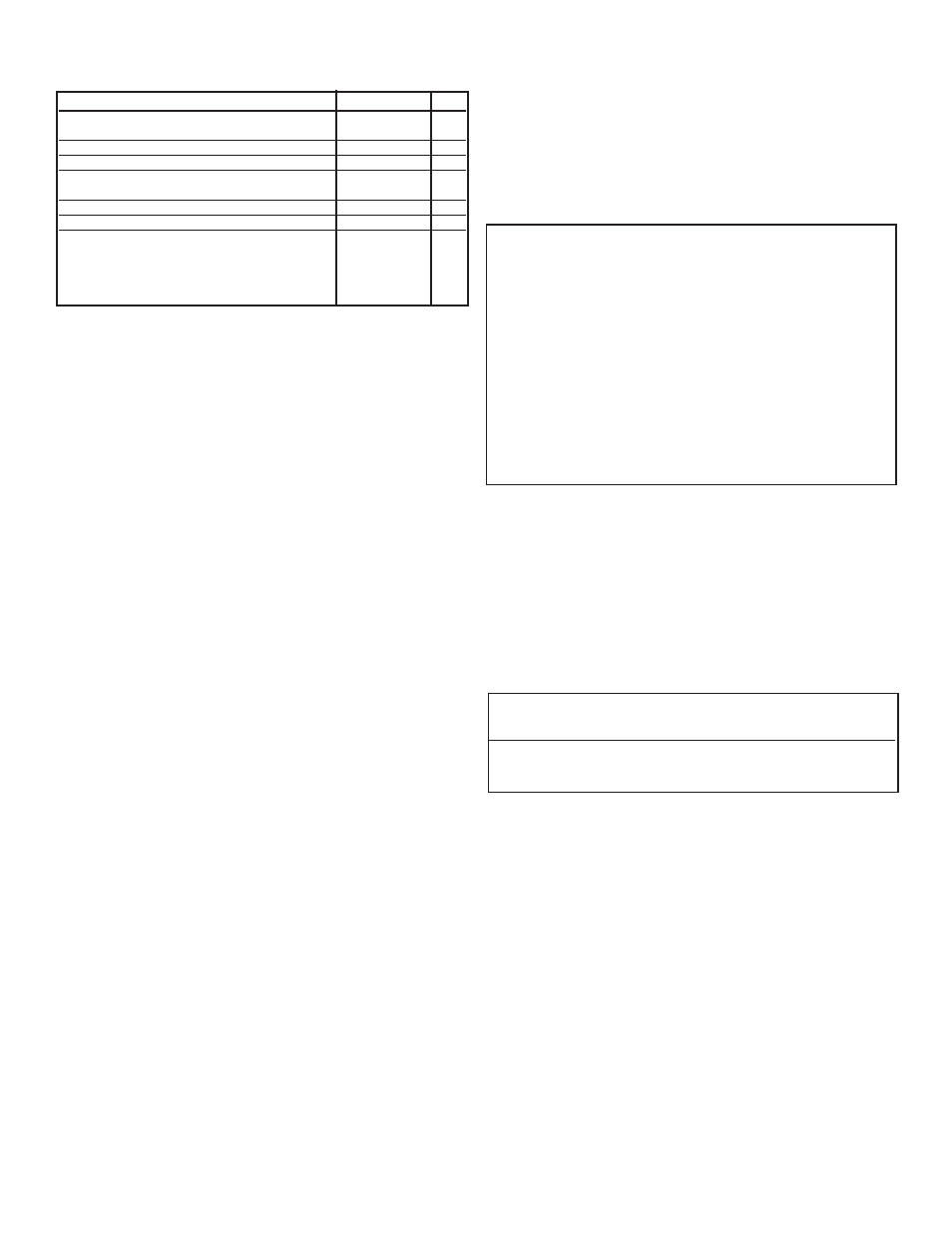
CONTROL PAD LED INDICATORS
The control pad LED’s indicate the following when illuminated (
FIG
9):
DESCRIPTION
COLOR
ITEM
Vehicle Engine running (ignition switch
is in the
ON
position) (
MOTORHOME ONLY
)
green
A
Park Brake engaged (
MOTORHOME ONLY
)
green
B
Park engaged (
MOTORHOME ONLY
)
green
C
Low Voltage (less than 13 VDC present
at controller)
red
D
ON/OFF (referencing power to control box)
green
E
Extend/Retract Mode
green
F
Leveler positions
Fully Retracted
solid green
G
Extended
green blinking
G
Extending/Retracting red
blinking
G
Fully Extended
solid red
G
TO LEVEL
For 5th Wheels, refer to MPD 71125 and MPD 87920 for Operation.
AUTO POSITION CONTROLS
Your keypad may have LEDs to indicate ‘EXTEND’ OR ‘RETRACT’ mode.
If the Auto position is already set or programmed,
• Press the ON button (
FIG
9-A) to activate the system.
• Press the AUTO button (
FIG
9-B).
• The levelers will extend and automatically reach the pre-set position.
• The system will check each Leveler to insure its foot is in contact
with ground. During this time, the control board “WAIT” LED will be
on (
FIG
9-C).
TO SET AUTO POSITION
1. Look at the keypad for your system. You have an automatic controller
if there is a button that says “AUTO” (
FIG
9-B).
2. To set the AUTO position
a. Manually get the RV to the position you want.
b. Then press the ON (
FIG
9-A) button one time, to turn controls off.
c. Press ‘EXT’ button (
FIG
9-D) 5 times.
d. Press ‘RET’ button (
FIG
9-E) 5 times.
e. Unit will respond by blinking all LEDS slowly.
f. Press ‘ALL’ button (
FIG
9-F) 3 times.
g. Press ‘ON’ (
FIG
9-A) then ‘RET’ ‘All’ to retract all Levelegs (
FIG
9-E
and 9-F).
TO SET AIR DUMP MODE
1.
If LEDs blink left-to-right and back again, your RV has the Air
Dump feature.
a. To enable Air Dump, press the “DRIVER” button (
FIG
9-G)
three
(3) times. The driver side LEDs (
FIG
9-H)
will illuminate for 3 sec-
onds and shut off. Press “ON” (9-A), then “RET” “All” to retract
all Levelegs (
FIG
9-E and 9-F).
b. To disable Air Dump, press the “PASSENGER” button (
FIG
9-I)
three (3) times. The passenger side LEDs (
FIG
9-J)
will illuminate
for 3 seconds and shut off. Press “ON” (
FIG
9-A)
, then “RET”
“All” to retract all Levelegs (
FIG
9-E and 9-F)
c. If the Air Dump feature is not set or has never been configured,
the system will wait for 30 seconds. It will default to “Not
Configured” and the passenger side LEDs will illuminate for
3 seconds and shut off.
2. To change Air Dump from enabled to disabled or vice versa, have
the engine running, the park brake engaged and the transmission in
PARK.
a. Press “ON” (
FIG
9-A)
to turn the controls off.
b. Press the “EXT” button (
FIG
9-D)
ten (10) times.
c. Press the “RET” button (
FIG
9-E)
ten (10) times.
d. The LEDs will blink left-to-right and back again. Go up to step
3 above and follow the directions to either enable (step 3-a) or
disable (step 3-b) the Air Dump feature.
e. To check the status of the Air Dump, wait 30 seconds and see
which LEDs illuminate. If the air dump is enabled, the driver
side LEDs (
FIG
9-H)
will illuminate and if the air dump is dis-
abled, the passenger side LEDs (
FIG
9-J)
will illuminate.
TO MANUALLY DUMP THE AIR BAGS
a. Engine must be running.
b. Transmission must be OUT of Park/Neutral.
c. Parking brake must NOT be engaged.
d. Atwood Levelegs keypad is NOT on. Lights inside the ON switch
are not lit.
e. Press the FRONT + REAR + ALL buttons to dump air from air
bags. (Note: Air dump feature does need to be enabled for this
feature to work.)
f. Air bags dump in approximately 20 seconds and air bags refill
60 seconds from the start of the air dump.
These controls have the following features to facilitate leveling:
•
TO MAXIMIZE AVAILABLE LEVELER STROKE During the initial activation of a
pair of levelers following the
ALL
extend activation, for every six (6) sec-
onds the first pair of levelers extend, the opposite pair of levelers will
retract for two (2) seconds. This process will repeat for the first 60 con-
tinuous seconds of extension of first pair of levelers.
•
FULL EXTENSION If a leveler is fully extended, its corresponding LED will
indicate this and further operation of that pair of levelers in the extend
direction is prevented. If the switch is held on, the second leveler of the
pair will operate with its alternate pair partner leveler. (i.e., if the front
two levelers are extending and the left front leveler becomes fully
extended, the right front leveler will continue to operate and the right
rear leveler will start to extend.) This is to keep the frame from twisting.
•
LOAD COMPENSATION If one leveler becomes disproportionally more
loaded than its pair partner, power will shut off to the first leveler. The
second leveler will continue to operate until the load is more balanced
between the pair of levelers. Power to the first leveler will then resume.
TO RETRACT
1. Ensure slideout rooms are fully retracted (in their inboard position).
2. Press the
ON
button (
FIG
9-A).
3. Press the
ALL
button (
FIG
9-F) and
RETRACT
button (
FIG
9-E) simultane-
ously and release. Levelers will retract automatically to their fully
retracted position. The leveler indicator LEDs will blink red (
FIG
9-H
or 9-J) during this activity.
4. Once levelers are fully retracted, level indicator LED
(
FIG
9-H) will be
solid green.
NOTE
: After operating levelers, the position LEDS for all the levelers must be
solid green before the vehicle is to be moved. A visual examination of
all the levelers outside the motor home is recommended to insure
levelers are fully retracted.
ƽ
CAUTION
PRODUCT DAMAGE
•
Do not move vehicle until levelers and landing legs are fully retracted.
•
Damage can occur to levelers, coach and surrounding property if the
levelers are not fully retracted prior to vehicle being moved.
5. Press the
ON
button (
FIG
9-A) to turn off power to the control pad.
SYSTEM PROTECTION FEATURES
Automatic Retract
•
Anytime the engine is on, if the vehicle brake is depressed and
transmission is taken out of park, the levelers will fully retract
automatically.
•
During auto retraction, an alarm will sound and all LEDs will blink on
and off.
Nine Cycle Maximum
•
The controls will shut off for 15 minutes any time nine (9) full
retractions occur in less than 30 minutes.
•
When this occurs, all four system status lights blink off and on.
•
This sequence can be over ruled by turning the ignition off, then back on.
Low Voltage Protection
•
If the voltage falls below 10.5 VDC, leveler operation will cease
and the low voltage LED will flash.
•
Controls will be inoperable until battery voltage climbs above 13
VDC, at which time leveling functions will resume.
Manual Override
• To Manually Extend or Retract Leveler, use a 1/2˝ socket on Drive
Nut on the end of the motor (
FIG
10-A).
Rotate nut counter clockwise (looking from bottom end of nut
[
FIG
10-B]) to extend leveler.
NOTE
: It takes 500 revolutions of nut to extend/retract leveler 1˝.