Operation, Pre-delivery preparation, Caution – atwood Levelegs System User Manual
Page 2: Warning
2
MOTOR HOME SIGNAL WIRE HARNESS
1. Connect the motor home signal wire harness (
FIG
3-I) to the con-
troller (
FIG
3-K).
2. Motor home signal wire harness to be configured as follows (
FIG
8):
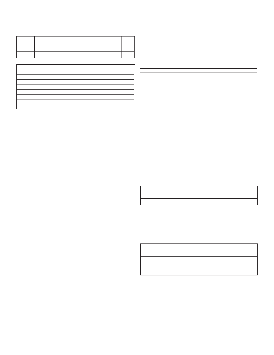
ITEM
DESCRIPTION
QTY
A
43025
Molex
®
Micro-fit 3.0,8 circuit receptacle
1
B
43030
Molex
®
Micro-fit 3.0 female tin terminal
4
C
Unshielded 20 AWG multiconductor cable
1
Pin Requirements - (
FIG
8)
CONNECTOR PIN
DESCRIPTION
(
REFERENCE
)
FIGURE
COLOR
P1
Park Brake
D
white
P2
Transmission
E
green
P3
N/A
F
N/A
P4
N/A
G
N/A
P5
Foot Brake
H
red
P6
N/A
I
N/A
P7
Ignition*
J
black
P8
N/A
K
N/A
* Install with a 3 AMP in-line fuse to chassis ignition wire.
3. Crimp the contacts with the approved Molex
®
die.
4. Crimped contacts must withstand a minimum nine (9) pound pull force.
5. Terminate the sleeve of multi-conduit cable to within 1˝ of connector
(
FIG
8-L)
6. Length of harness “as required” to easily connect control pad to
controller (
FIG
8-M).
POWER CONNECTIONS (FIG 3)
A - Driver Front Leveler
G - Yellow (+) Motor Gear Box Lead
B - Passenger Front Leveler
H - Control Pad Wire Harness
C - Driver Rear Leveler
I - Motor Home Signal Wire Harness
D - Passenger Rear Leveler
L - Female Connector (Delphi
®
)
E - 125 Resetable Circuit
M - Male Connector (Delphi
®
)
Breaker for 2 AWG
O - Air Bag Dump Valve (optional)
battery wire
P - Air Bag Fill Valve (optional)
F - Red (-) Motor Gear Box Lead R - Male connector (Deutsch
®
)
S - Female connector (Deutsch
®
)
Controller to Battery
1. Connect the controller to the chassis 12 VDC battery through the
manual reset circuit breaker or fuse (
FIG
3-E).
2. Connect the controller to the battery through 2 AWG wire (
FIG
3-N).
3. Terminate 2 AWG wire (
FIG
5-A)
power wire to controller through a
2 AWG 1/4” ID ring terminal (
FIG
5-B)
4. Attach ring terminal to controller with following components:
•
#10 conductive washer
FIG
5-C
•
#10 lock conductive washer
FIG
5-D
•
10-32 conductive nut
FIG
5-E
Note: Torque nut (
FIG
5-E) to 20-25 in/lbs.
Levelers to Controller
Controller must be connected to levelers through a wire harness
using 8 or 10 AWG wire.
•
Use 8 AWG wire for leveler rated above 10,000 lbs
or wire runs longer than 30 feet.
•
Use 10 AWG wire for levelers rated at or below 10,000 lbs
or wire runs shorter than 30 feet.
Leveler End (
FIG
6)
A. Use the following Delphi
®
or comparable components to terminate
both leads coming from the controller to lower motor connector
of the 7.5K or 10K levelers.
•
12065863
Connector
Male
FIG
6-A
•
12052172
Terminal
Male
FIG
6-B
•
12034170
Cable Seal
FIG
6-C
•
12059897
Secondary Lock
FIG
6-D
1. Strip wires (
FIG
6-F) back about 3/8˝ (
FIG
6-E).
2. Slide cable seal (
FIG
6-C) onto wire with neck of cable seal facing
stripped metal in wire.
3. Push cable seal forward to align neck of cable seal with edge of
insulation of stripped back wire end.
4. Put stripped wire into crimp wings closest to mating end of termi-
nal (
FIG
6-B) and neck of cable seal (around insulation) into sec-
ond set of wings furthest from mating end.
5. Crimp metal from wire to first set of wings.
6. Crimp cable seal neck (around insulation) to second set of wings.
Then snap secondary lock (
FIG
6-D) onto connector (
FIG
6-A).
7. Minimum of strength of core crimp without insulation crimp
should withstand a pull of 300 N (75 lbs).
8. Crimp dimensions:
CORE
:
2.4mm (.094˝) high
5.05mm (.20˝) wide
INSULATION
:
7.6mm (.30˝) high
7.4mm (.30˝) wide
NOTE
: Insert the terminals into the connectors with the flat bottoms
of the terminals oriented toward the connector locks.
B. To terminate 8 gage wire leads from the controller to 15K levelers
use the following components:
ITEM
PART
ATWOOD P
/
N
DEUTSCH P
/
N
S
connector, female
66627
DTHD04-1-8P
FIG
15-S
S2
contact pin
66635
0460-204-08
FIG
15-S2
R
connector, male
66636
DTHD06-1-8S
FIG
15-R
R2
contact socket
66634
0462-203-08
FIG
15-R2
Auto Position Controls
1. To terminate leads from the wire harness connected to the levelers
use the following components:
•
8 or 10 AWG wire
FIG
5-A
•
8 or 10 AWG, ring terminals
FIG
5-B
10 AWG
8 AWG
42816-0512 42516-0512
Connector
FIG
7-A
42815-0011 42815-0331
Terminal
FIG
7-B
2. Trim lead 5/16˝
FIG
7-C.
3. Pin connectors to match pins in Auto Position Control Board as
shown in
FIG
3.
4. Insert Molex
®
connector from wire harness into control board.
5. To address communication with the air suspension system, the con-
troller must have a single signal lead provided for “Air Dump”
(
FIG
3-O) and a single signal lead provided for “Air Fill” (
FIG
3-P).
PRE-DELIVERY PREPARATION
Wipe any excess fluid from the top of the foot before delivery.
OPERATION
BEFORE OPERATING THE LEVELERS
ƽ
CAUTION
PERSONAL INJURY
•
Stand clear of the vehicle.
Before operating the levelers, you must do the following:
1. Park the vehicle on a level site. Check for rocks, holes, or other
obstructions. Warn all persons to stand clear of vehicle.
2. For a motorhome,
• Put the vehicle transmission in
PARK
.
• Engage the vehicle
PARKING BRAKE
.
• Have the vehicle engine running.
3. Do not extend the slideouts until coach is level.
ƽ
WARNING
VEHICLE CAN TIP
•
Levelers must be on firm solid ground or surface prior to operation.
Soft/spongy ground may allow levelers to sink.
•
Area below and around leveler must be clear of obstructions.
•
Do not place blocks under the leveler for additional ground clearance.
LEVELERS ARE SHIPPED IN THE ERROR MODE STATE.
To take controls out of error mode state, complete a successful
ALL RETRACT (as defined in items 1-3) under TO RETRACT.
4. Put stripped yellow (+) wire end into contact pin (
FIG
15-52) and
crimp together. Crimp must withstand a minimum pull of 75 lbs.
5. Put stripped red (-) wire end into contact socket (
FIG
15-R2) and
crimp together. Crimp must withstand a minimum pull of 75 lbs.
6. Insert the contact pin (
FIG
15-S2) into the female housing (
FIG
15-S)
until it is secured. Then slip seal into housing.
7. Insert the contact socket (
FIG
15-R2) into the male housing (
FIG
15-
R) until it is secured. Then slip seal into housing.