American Expedition Vehicles Tummy Tucker – TJ Rubicon models User Manual
Page 5
Installation Instructions:
Tummy Tucker™ – TJ Rubicon models
Nth30116 v4.doc
page 5 of 13
www.aev-conversions.com
Fig. 6
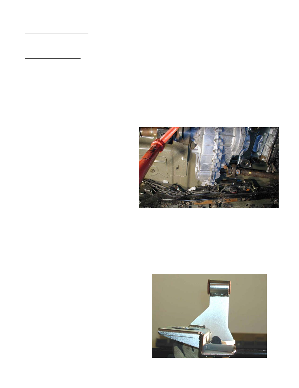
Fig. 7
Step 6e: Rearrange Wiring. As you may have already done at this point, some of the wires leading to
and from the four connectors that were mounted to the locker pump bracket can be unplugged and
rerouted around each other to better suit the new location. Once this is done, the wires will need to be
zip-tied to the frame-mounted fuel/brake lines.
Step 6f: Reroute Hoses. There are some simple modifications to allow the hoses to reconnect:
-
remove the large (about 1”) diameter plastic ‘convolute’ sheathing that holds the rear locker pump
hose and wires along with the larger air intake hose coming from the fuel filler area. By zip-tying the
intake hose to the fuel and brake lines along the driver’s frame rail, you can ‘save’ a large amount of
this intake hose length – it will be more than enough to reattach it to the plastic ‘T’ at the back of the
locker pump bracket. You may need to gently pull a little extra length from above the fuel tank as
well. There will be enough to allow you to cut off about 3” of extra hose.
-
Use the 3” of intake hose plus the supplied ¼” barbed union fitting to reconnect the front locker pump
to the plastic ‘T’ (The ‘T’ should be at the very back of the bracket, with the rear locker hose straight
out instead of bent 90 degrees as it was originally). Secure the remaining small hose and wires that
go to the rear axle along the left-rear upper control arm or as appropriate to allow full suspension
motion, etc.
-
Next, cut 7.5” off of the small diameter
hose going to the front axle and reattach it
to the front locker pump – you will need to
remove the last tape wrap and turn the
hose around 180 degrees to fit onto the
pump.
-
Use the 7.5” piece of small tubing and the
supplied 3/16” barbed union fitting to
extend the rear locker’s small hose. This
should make the rear hose long enough to
reattach to the rear locker pump.
Figure 6 shows how everything should be
hooked up again, with nothing stretched too
tight or hanging where it could be damaged. Ideal routing of the various harnesses should be apparent
and can be held in place with a few added zip-ties. It is especially recommended to make sure that none
of the hoses/lines are hanging free and close to where they could get tangled in the front drive shaft – if
you keep everything ‘inside’ the locker bracket’s flanges, you will not have any problems. Final
attachment to bracket to the TT will occur in step 12 after the TT is bolted in.
Step 7: Remove Stock Transmission Mount. Remove the four bolts that attach the bracket to the rear-
underside of the transmission (5/8” heads) – there is no need to remove the isolator itself from the
adapter bracket. Once the bracket is loose, slide it rearward until the exhaust steady rest isolator slips
off of the hanger pin (solid rod that is welded to the pipe ahead of the catalytic converter.) These parts
will not be reused with the TT.
Step 8: Remove exhaust hanger bushing. You will
re-use the exhaust steady rest isolator bushing
from the original bracket. To remove it, note that
the rear (as it was installed on the Jeep) end of the
isolator has a smaller lip on it than the front – push
the isolator out from this end towards the front
using a ¾” socket (using a larger socket will shear
off the small lip). Replace the isolator in the same
orientation in the tube on the new bracket – it will
be much easier if white-lithium grease is sprayed
inside the tube. See figure 7 for completed
conversion orientation.