Total power solutions – Alpha Technologies XM2-300HP Wall-Mount Rack User Manual
Page 2
Alpha Technologies reserves the right to make changes to the products and information contained in this document without notice.
Copyright © 2010 Alpha Technologies. All Rights Reserved. Alpha
®
is a registered trademark of Alpha Technologies. member of The Alpha Group™ is a trademark of Alpha Technologies.
746-221-C0-001 Rev. A (10/2010) To report errors or omissions in this document, send email to [email protected]
For more information visit www.alpha.com
United States
Bellingham, Washington Tel: 360 647 2360 Fax: 360 671 4936
Canada
Burnaby, British Columbia Tel: 604 436 5900 Fax: 604 436 1233
member of The Group
TM
Total Power Solutions
Installation Procedure:
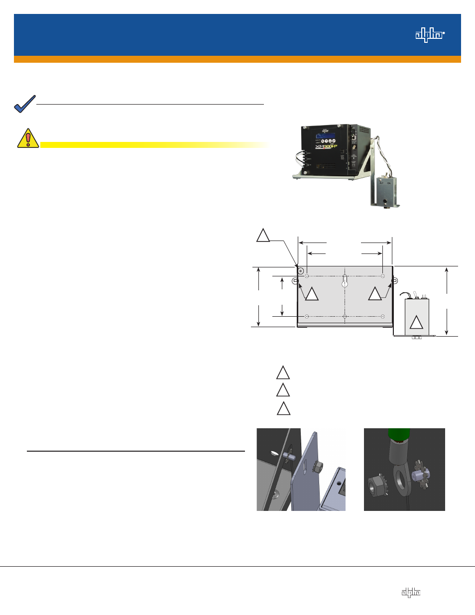
1. The dimensions of the shelf are 6.94" (8.9" with XM2-
300HP installed) H x 10.12" W x 8.58" D (176.3mm /
226.0mm x 257.0mm x 218.0mm). Select a location that
allows sufficient clearance on the top, bottom and sides for
cabling required for the installation.
2. For center mounting, locate one stud and drill pilot hole.
Install first user-supplied 5/16" lag bolt and hang the
shelf using keyslot. Mark and drill second hole and install
second lag bolt. Secure both lag bolts once shelf is
positioned.
3. For corner mounting inside of enclosures, use drawing to
locate the four corner holes. Use four user-supplied 5/16"
bolts to mount shelf.
4. Install the SPI to the SPI bracket and torque to 130 in-lbs.
Follow the proper stack up as shown in Fig. 4 and mount
the SPI bracket onto either #10-32 (item 2, Fig. 3) studs
and tighten supplied #10-32 nut and lock washer.
The populated shelf weighs approximately 40 lbs (18.14kg). The
installer must verify the wall is capable of supporting the loaded
shelf. Direct mounting to a wall stud and use of customer-supplied
3/4" plywood backing is required.
Installation Instructions
Wall-Mount Shelf (WMS) for XM2-300HP
8.00" / 203.2mm
10.12" / 257mm
6.94"
176.3mm
Fig. 3, Mounting hole layout and SPI bracket
1
#10-32 ground stud
2
#10-32 SPI mounting bracket stud (2 plcs.)
4.00"
101.6mm
6.09"
154.7mm
2
2
1
Fig. 4, SPI Hardware
stack up
Install the system in a sheltered, weather-protected location
inaccessible to the general public.
NOTE:
CAUTION!
For proper operation of the Power Supply and Communications
Module, external grounding of the shelf is required.
IMPORTANT:
R
ec
ommended Tools and Materials:
• Ratchet with 1/2" and 5/16" (or metric equivalent) sockets
• Level
• Two user-supplied 5/16" x 3" (or metric equivalent) lag bolts
• 1" Torque Wrench
• Stud finder (optional)
• Drill with 1/4" (or metric equivalent) drill bit
• Tape measure (optional)
5. The shelf is connected to ground via the
#10-32 ground stud circled in Fig. 3. Follow the proper
stack up as shown in Fig. 5 to attach the supplied lock
washer, #10-32 nut and user-supplied ground wire. Refer
to applicable codes to determine additional grounding
requirements.
For Power Supply installation and connection, refer to the
XM2-300HP Technical manual (p/n 017-877-B1) at www.alpha.com
Fig. 5, Ground wire
stack up
3
3
SPI