Installation, Continued, 1 installation in an xm series 2 power supply – Alpha Technologies USM2.5 Status Monitor User Manual
Page 6
018-041-C0-002 Rev. B
6
1. Installation
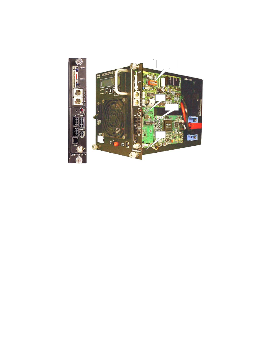
12. Using the two captive screws just behind the face plate, secure the transponder
to the inverter module.
13. Verify that the 10 position jumper on the transponder is set to the correct
battery pack voltage.
14. Verify that the 8 position DIP Switch on the USM2.5 is set correctly. Refer to the USM2.5
operators manual (Alpha p/n 704-683-B0).
15. Set the inverter module onto the guides, and side it 1 or 2 inches into the power supply.
16. Reconnect the ribbon cable to the inverter module, and latch the two retaining
clips over the ribbon cable plug.
17. Slide the inverter module fully into the power supply, and tighten the thumb
screws. Set the BATTERY BREAKER to the ON position.
18. Verify after 10-30 seconds, the Smart Display on the power supply reads
'OPERATION NORMAL'.
19. Download Alarm Profile from NetMentor to initiate appropriate mode of operation.
20. Verify that, after approx. 1 minute, the 'CPU' LED on the front of the transponder
is blinking, if not, press the RESET button behind the hole next to the LEDs
(see Fig. 1-2).
1.1
Installation in an XM Series 2 Power Supply,
continued
Figure 1-1 Transponder Installation
8 Position DIP
Switch
10 Position
Jumper
Captive
screw
Captive
screw