Alpha Technologies Undermount PWE Series User Manual
Page 2
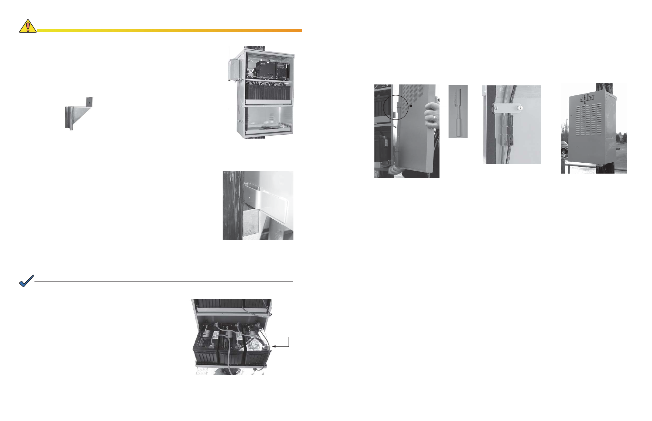
Fig. 6 Mounting the Lower Bracket
for Wood Poles
Fig. 4, UBE Attached
Fig.7, UBE with Batteries, Wiring Cable Kit
Positive terminals
positioned toward
front of enclosure
033-089-C0-001
033-089-C0-001
Fig.10, Installation Complete
Fig. 9, Cable Retainer
Fig. 8, Mounting New Door with
Suspended Hinge
B. Securing the Lower Bracket to the Pole
To maintain the integrity of the enclosure, take extra care to ensure all fasteners are properly tightened.
CAUTION!
Fig. 5, There is an optional 8"
extended bracket available.
Fasten the center stud using the provided 1/4-20 KEPS nut. There
will be two holes remaining, one on either side of the center stud. If
necessary, use your drill to ensure the 13/64" holes are clear.
Insert the provided screws (#10-32 x 34") into the holes located to
the side of the center screw. Using the fl at washers and Nylock nuts
provided, complete securing the unit. Repeat Steps 4 through 7 for the
left side of the unit.
6.
7.
For Concrete or Steel Poles:
To secure the UBE to a concrete or steel mounted enclosure, follow
the instructions provided for securing the bracket to a wooden pole, but
use customer-supplied stainless, galvanized, or equivalent, pole straps
to fasten the lower bracket to the pole. All other instructions apply to
both types of mounted enclosures.
C. Connecting the Batteries
Place the batteries, with the positive terminals oriented
toward the front of the enclosure, on the slide tray. See
Fig. 7.
Use battery cable kit (p/n 875-574-20) to wire the
batteries in the UBE together.
Open the top tray in the original enclosure, following
the diagrams on the next page, attach the battery cable
kit (p/n 875-574-20) to the batteries. See Fig. 11.
Connect the two tiers of batteries, and plug the
batteries into the power supply.
1.
2.
3.
4.
For Wood Poles:
Place the bracket in the UBE backstrap and mark the hole for the lower
mounting bracket. If required, use the bolt provided in the backstap to
hold the bracket in place.
Using a 3/4" bit, drill a hole completely through the wooden pole.
Secure the bracket with a 5/8" bolt, washer, and nut. Hand tighten.
Use a rubber mallet to ensure the bracket is seated tightly against the
enclosure back strap and tighten securely. See Fig. 6.
You are now ready to add and connect the batteries. See Fig. 7.
1.
2.
3.
4.
D. Completing the Installation
Mount the new door to the unit. To account for PWE variances, the door mounts with a suspended hinge. See
Fig. 8.
Using the provided cable retainer, located on the inside of the new door, secure the battery cables to the
inside of the door and close the enclosure. See Fig.9.
1.
2.
E. Installing Optional Features
Tamper Switch
If you are using a tamper switch, attach the magnet to the new door.
If you do not have a tamper switch installed, follow the instructions provided with the PWE enclosure and the
tamper switch kit.
Battery Heater Mat
Add the heater mat to the bottom of the empty enclosure or optional battery tray.
Route the cable through the same cable retainer used by the battery cables.
Plug the line cord into the receptacle.
•
•
1.
2.
3.
NOTE:
If you are using an optional battery heater mat, it must be installed before adding the batteries to the enclosure.