Alpha Technologies Undermount PWE Series User Manual
Power, A. mounting the ube to the existing enclosure
The Undermount Battery Expansion Enclosure (UBE) increases capacity of PWE Series enclosures, providing space for
three additional batteries. The UBE-PWE easily and quickly attaches below an existing PWE-3 pole-mounted enclosure.
Tools and materials:
A. Mounting the UBE to the Existing Enclosure
Follow these steps to mount the UBE to the existing enclosure. See
Section B for separate bracket mounting instructions for wood, concrete or
steel, or wall mounted enclosures.
Remove the door from the existing unit. This door will be replaced by
the new door.
Use the templates provided to mark the drill holes. Carefully align the
appropriate template with the corresponding front and bottom side
edge of the existing enclosure and tape in place.
1.
2.
Fig. 2, Position UBE
Drill with 17/64", 13/64", and 3/4" bits
•
Tape for positioning template
•
Rubber mallet
•
Four #10-32 x 3/4" pan head screws, washers, KEPS nuts
(provided)
•
Center punch
•
Two 7/16" wrenchs
•
#2 Phillips screw driver
•
Two 1/4"-20 KEPS Nuts
(provided)
•
After confi rming the position of the template, use a center punch to mark
the drill locations. Repeat for the other side. See Fig. 1
Using a drill with a 13/64" bit, drill two holes through the marked drill
locations on each side of the UBE. With the 17/64" bit, drill or enlarge each
center hole. There should now be three holes on each side of the existing
enclosure.
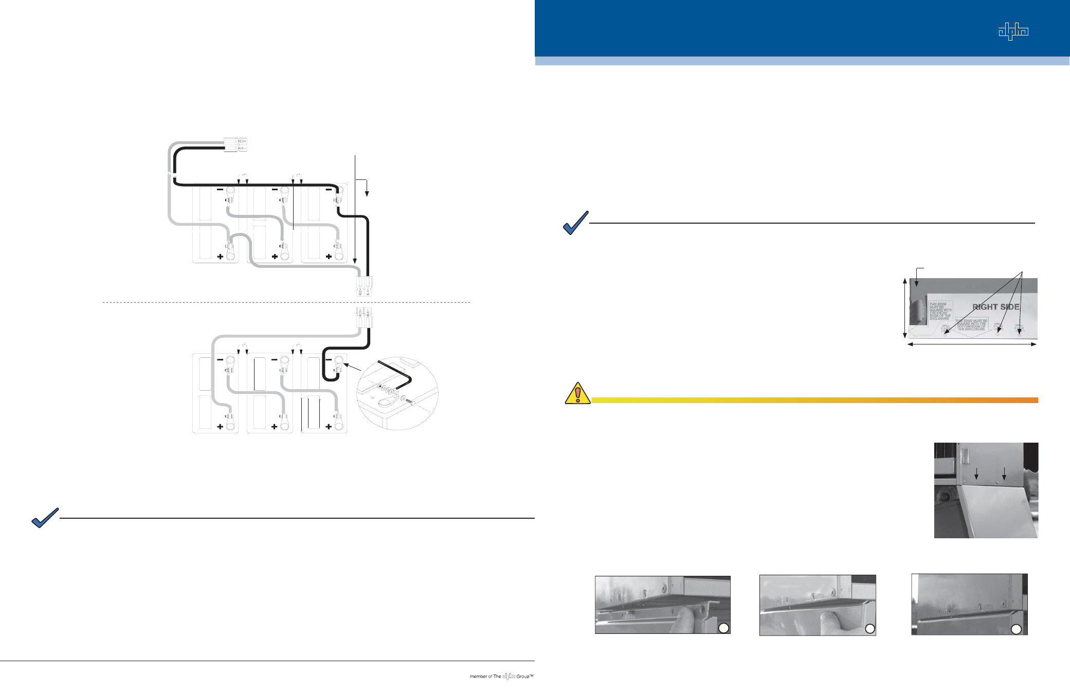
Position the right side of the UBE inside the bottom lip of the PWE. Insert
the stud, located at the top edge of the UBE, into the 17/64" drilled hole.
You can use your rubber mallet to aid in positioning the unit. See Figs. 2
and 3.
3.
4.
5.
CAUTION!
The template must be fl ush with both edges of the enclosure or the screw holes will not align properly.
Oversized or poorly placed holes may cause the joint to fail.
Fig. 3, Maneuver Side of UBE into Existing Enclosure
Power
®
NOTE:
To fi t properly into the PWE, the pole mount bracket bolt must not protrude from the center dimple of the bracket. If
the bolt is protruding, it needs to be cut or ground fl ush with the front face of the pole mount bracket.
1
3
2
United States
Bellingham, Washington Tel: 360 647 2360 Fax: 360 671 4936
Canada
Burnaby, British Columbia Tel: 604 430 1476 Fax: 604 430 8908
For more information visit www.alpha.com
Alpha Technologies reserves the right to make changes to the products and information contained in this document without notice.
Copyright © 2006 Alpha Technologies. All Rights Reserved. Alpha
®
is a registered trademark of Alpha Technologies. member of The Alpha Group™ is a trademark of Alpha Technologies.
033-089-C0-001(03/2006)
Wires pass
through hole in
shelf
1A
2A
3A
1B
2B
3B
Fig. 11, Battery Wiring Diagram
PWE
UBE
Part of Battery Cable Kit (p/n 875-574-20)
NOTE:
There are small holes on the bottom edge of the UBE. They are not load-bearing. Do not use these holes for support.
Undermount PWE Series Battery Expansion Enclosure
Field Installation Guide
Fig. 1, Marking Drill Holes
Align template with both the vertical and
horizontal edges of the enclosure.
Drill holes
Side panel of existing
enclosure