Handle installation – Alpha Technologies Portable Generator Wheel Kit and Handle Assembly User Manual
Page 3
3 of 6
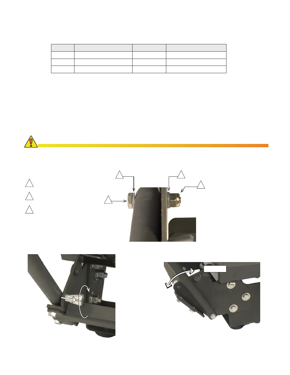
. Position the handle on the outside of each side of the foot bracket assembly.
2. Fasten the handle to the brackets with the /4-20 hardware as shown below (Fig. 7) and tighten each nut until
snug .
3. The portable generator handle is now ready for use. To transport the generator, fold the handle down, verifying
the spring-loaded locking pins engage. To place the handle in the "stowed" position, pull the locking pins out and
rotate each /4 turn (Fig. 8). To place the handle in the "storage" position, push the handle toward the generator
until it stops between the two plastic handle stops (Fig. 9). To return the handle to the transport position, rotate the
spring-loaded locking pins back /4 turn, allowing them to drop into position. Pull the handle down until it engages
the locking pins. The generator is now ready for transport.
Handle Installation:
Requires the following:
Quantity Part description
Part number
Tool required
2
/4-20 x .75" hex bolt
630-423-2
7/6" open-end wrench
2
/4-20 Nylock nut
634-030-2
7/6" socket
4
1/4-20 flat nylon washer
633-079-0
N/A
B
A
C
B
Transport
Storage
Fig 8., Handle Locking Pin Operation
(Pull out, rotate 1/4 turn)
/4-20 x -3/4" bolt
1/4-20 Nylon flat washers
A
B
C
/4-20 Nylon Lock Nut
Fig. 7, Handle Assembly Detail
Fig 9., Handle Positions
Both spring-loaded locking pins must be fully engaged before and during transport. Failure to fully
engage the locking pins could result in damage to the handle.
CAUTION!