Installation procedure, continued, Fig. 8, dsm3 front panel connections, Fig. 9, dsm3x front panel connections – Alpha Technologies DSM3 for XM3 - Quick Start Guide User Manual
Page 6
6
746-114-B5-001 Rev. B (04/2013)
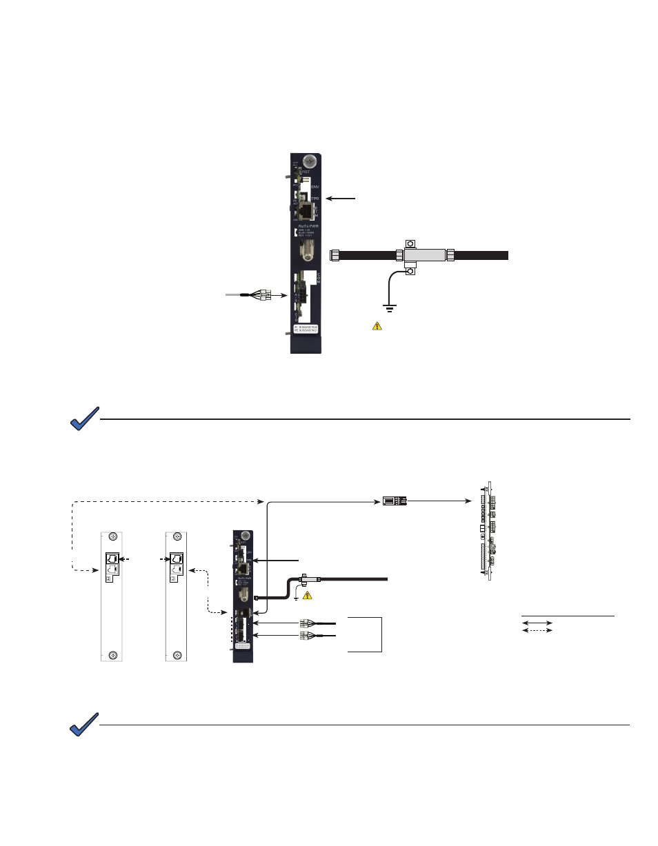
Fig. 8, DSM3 Front Panel Connections
To Battery Sense Wire Harnesses
Tamper Switch Connector
RF Cable to Headend
“Master”
XM3
Generator (ECM)
(Alpha p/n 744-726-XX)
ECM Technical Manual p/n 744-862-C0
available at: www.alpha.com
ECM Interface (Alpha p/n 704-709-20)
To Battery Sense Wire Harnesses
Tamper Switch Connector
C
O
M
S
Y
S
C
O
M
S
Y
S
Battery String
Connectors
XM3 SI
(Serial Interface)
Card
System Port
Communications
Port
Communications
Port
Connections
Connections with more
than one power supply
Legend:
Required
Grounded Surge Protector
(Alpha p/n 162-028-10 or equivalent)
A/B
C/D (option on
DSM3x only)
XM3 SI
(Serial Interface)
Card
Fig. 9, DSM3x Front Panel Connections
Required
Grounded Surge Protector
(Alpha p/n 162-028-10 or equivalent)
Each power supply must have a unique address. Refer to Intelligent CableUPS technical manual
(p/n 017-882-B0), or the DSM3 Series Transponder technical manual (p/n 745-814-B11) for additional
information.
NOTE:
Installation Procedure, continued
9. Make Battery Sense Wire Kit connections (not required with Smart AlphaGuard). Refer to the battery diagrams provided
with the sense wire kit or reference the DSM3 Series Technical Manual (Alpha p/n 745-814-B11).
10. Connect the RF drop and make front panel connections as shown in Fig. 8 for the DSM3, or Fig. 9 for the DSM3x. The
DOCSIS specification for downstream power level is ± 15 dBmV. However, for optimal performance, set the level as
close to 0 dBmV as possible. RF attenuators or cable simulators may be required to obtain optimal downstream and
upstream RF levels.
RF Cable to Headend
Alpha Bus Cable
Refer to Fig. 9 when using a DSM3x in a system configuration with multiple
power supplies or AlphaGen generator.
NOTE: