Installation procedure, continued – Alpha Technologies DSM3 for XM3 - Quick Start Guide User Manual
Page 5
5
746-114-B5-001 Rev. B (04/2013)
Installation Procedure, continued
The following steps apply to both new installations or
removal/replacement of existing Communications Modules:
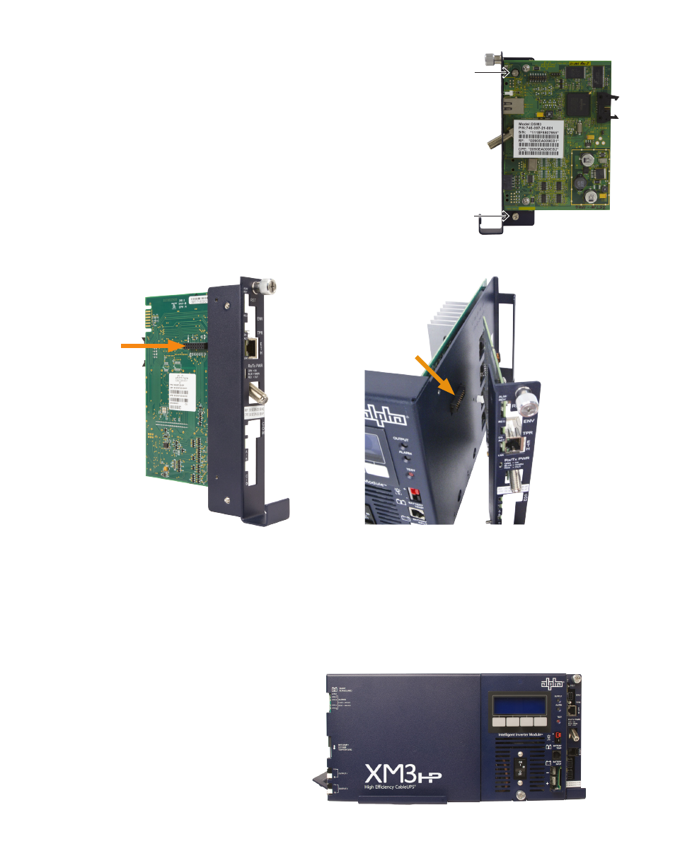
Fig. 7, Front Panel View of Completely Installed DSM3x in XM3-HP
Fig. 4, Captive Screw Locations
A
A
7. Reinstall the Inverter Module, tighten the two thumbscrews and
reconnect the front panel connections (tamper, temperature sensor,
battery harness, etc.).
8. Verify the recording of the cable modem MAC address (RF MAC) from the
front of the unit for network provisioning.
Fig. 5, 18-pin Connector
Fig. 6, Connecting the Communications
Module to the Inverter Module
5. Line up the 18-pin connector on the Communications Module
(Fig. 5) with the 18-pin socket on the Inverter Module and connect
the two units together (Fig. 6).
6. Fasten the Communications Module to the Inverter Module
by tightening the two captive screws. (Fig. 4, items A) It is
recommended the screws be tightened alternately, a few turns
at a time so the Communications Module aligns in parallel to the
Inverter Module.