Total power solutions, Test connection – Alpha Technologies AlphaNet IDH4 for XM3-HP Series - Quick Start Guide User Manual
Page 6
Total Power Solutions
member of The Group
TM
Alpha Technologies Inc.
3767 Alpha Way
Bellingham WA 98226
USA
Tel: +1 360 647 2360
Fax: +1 360 671 4936
Alpha Technologies Ltd.
7700 Riverfront Gate
Burnaby BC V5J 5M4
Canada
Tel: +1 604 436 5900
Fax: +1 604 436 1233
Alpha Technologies Europe Ltd.
Twyford House, Thorley
Bishop’s Stortford,
Hertfordshire
CM22 7PA
United Kingdom
Tel: +44 1279 501110
Fax: +44 1279 659870
Alpha Technologies GmbH
Hansastrasse 8
D 91126 Schwabach
Germany
Tel: +49 9122 79889 0
Fax: +49 9122 79889 21
AlphaTec Ltd.
339 Saint Andrews Street
Suite 101 Andrea Chambers
3307 Limassol
Cyprus
Tel: +357 25 375675
Fax: +357 25 359595
AlphaTEK ooo
Khokhlovskiy Pereulok 16
Stroenie 1 Office 403
109028 Moscow
Russia
Tel: +7 495 916 1854
Fax: +7 495 916 1349
Alpha Technologies
Suite 1903, Tower 1
33 Canton Road, Kowloon
Hong Kong, China
Tel: +852 2736 8663
Fax: +852 2199 7988
Alpha Technologies
Alpha reserves the right to change specifications without notice.
© 2014 Alpha Technologies Inc. All Rights Reserved.
Alpha is a registered trademark of Alpha Technologies.
746-257-B1-001 Rev. A (2/2014)
For more information visit www.alpha.com
Test Connection
With the IDH4 Series used in conjunction with the XM3-HP power supply, network connectivity can be verified via the COMM
menu on the XM3-HP Smart Display.
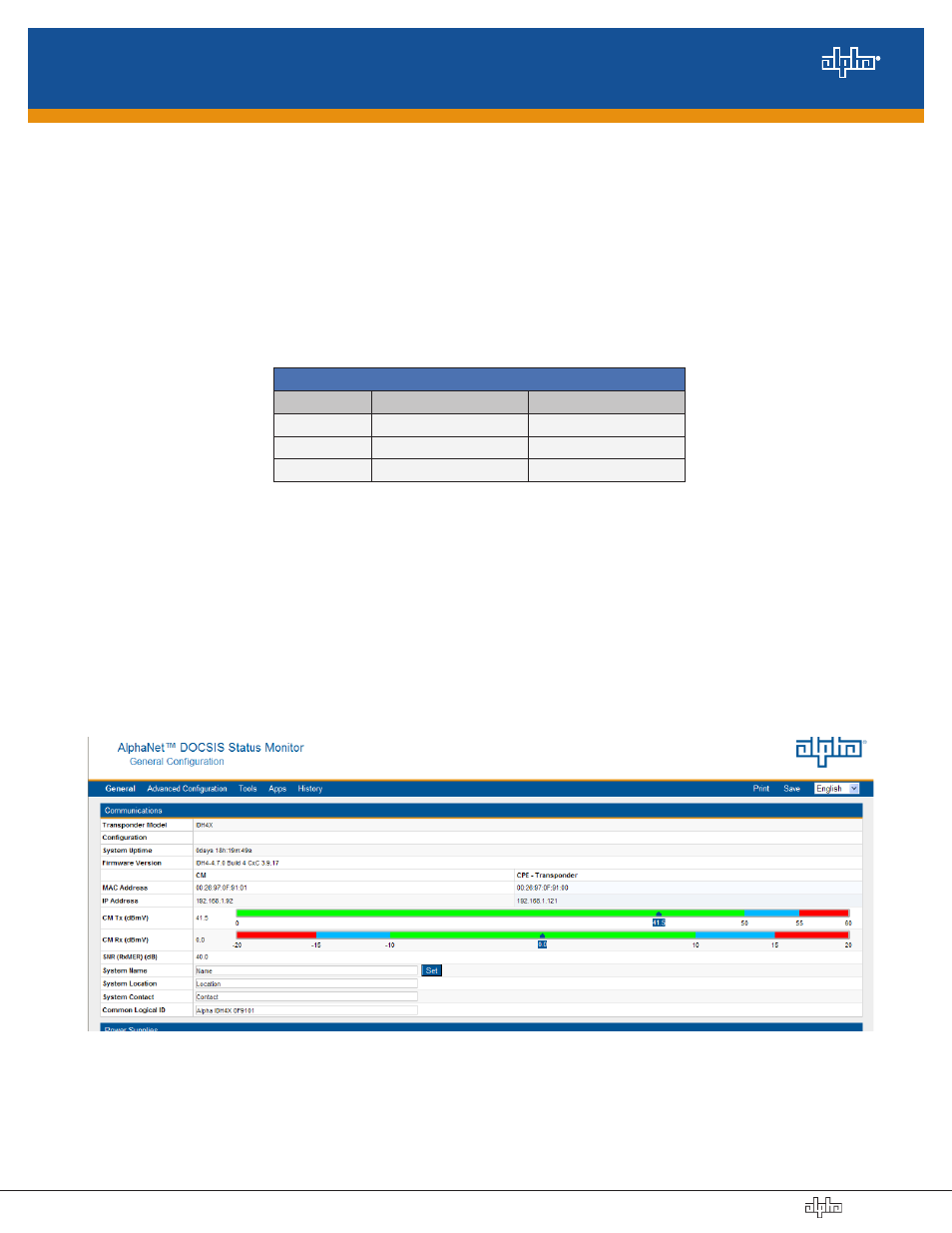
Connect a computer’s network port to the transponder’s Ethernet port using a standard network cable. Launch an Internet
browser and enter 192.168.100.1 into the address. The transponder will return the Web page shown below. The General
Configuration page shown below will appear and display connectivity, power levels, and power supply status information such as
alarms, output voltage, output current, and individual battery voltages. System Name, System Location, System Contact and
Common Logical ID may be edited on this page; when prompted for a User Name and Password, use "Alpha" and "AlphaGet".
Fig. 8, General Screen
1. Verify the power supply AC plug is connected into the AC outlet.
2. Switch Inverter Module battery breaker ON.
3. The IDH4 Series Status LEDs will all blink in unison upon initial power up. The RDY LED will then begin blinking steadily
indicating normal processor activity.
4. Verify the DS and REG LEDs are on solid. This verifies the Communications Module has registered an IP address on the
network.
5. Verify the RF LED is solid Green, indicating Upstream and Downstream Power is within the default specified range and the
Upstream RF Power is below the recommended +50 dBmV.
6. Verify no XM3 alarms are active.
RF Power Default Values
LED Color
Rx Range (dBmV)
Tx Range dBmV)
Green
+10 to -10
0 to +50
Blue
+15 to +10 and -10 to -15
+50 to +55
Red
>+15 and <-15
>+55
Table 1, RF Power Default Values
Initial Startup and Test / Returning the Unit to Service
(data values shown for illustration purposes only)