Installation / replacement procedure, continued – Alpha Technologies AlphaNet IDH4 for XM3-HP Series - Quick Start Guide User Manual
Page 4
4
746-257-B1-001 Rev. A (2/2014)
Installation / Replacement Procedure, continued
9. Reinstall the Inverter Module and tighten the two thumbscrews. Make front panel connections (tamper, temperature sensor,
battery sense, RF, etc.).
10. If not yet done, record the cable modem MAC address from the front of the unit and report it to the network manager for
network provisioning. For Dual IP applications, the CPE MAC address should also be recorded.
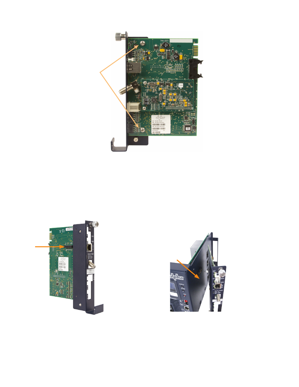
Fig. 4, The 18-pin Connector
Fig. 5, Connecting the Transponder to the Inverter Module
7. Line up the 18-pin mating connectors on the IDH4 Series and the XM3-HP Inverter Module. Gently push the IDH4 Series
into the Inverter Module until the 18 pin mating connector is properly seated.
8. Fasten the IDH4 Series to the Inverter Module by tightening the two captive screws. It is recommended that the screws
be tightened alternately, a few turns at a time so the transponder aligns in parallel to the Inverter Module.
Captive Screws
Fig. 3, Captive Screw Locations
- AlphaCell GelCell Series (32 pages)
- FXM 650, 1100, 2000 UPS (96 pages)
- Cordex 48-1.2kW (68 pages)
- Radium MiniBay (57 pages)
- Fiber Backhaul Enclosure (FBE) (19 pages)
- FBE2322 Enclosure System (38 pages)
- FlexNet PMR, GMR Series (49 pages)
- Te25xh (38 pages)
- FlexNet MPS48-12M - Technical Manual (33 pages)
- FlexNet MPS48-12M - Quick Start Guide (2 pages)
- FlexNet ELPM 300-48D (25 pages)
- FlexNet FMPS (40 pages)
- FlexPoint AX Series (34 pages)
- FlexPoint FPR1207-F - Technical Manual (18 pages)
- FlexPoint FPR1207-F - Quick Start Guide (2 pages)
- AlphaGen PN-6x-T 7.5kW 48VDC - Installation and Operation Manual (79 pages)
- AlphaGen CE-3x2 5K-T 48Vdc (95 pages)
- AlphaGen PN-6x-T 7.5kW 48Vdc (95 pages)
- AlphaGen 3.5_5.0kW Kohler COM5 (80 pages)
- Security Bar Field For UPE-3, UPE-6, UPE-M3, UPE-M6, PN Series and CE Series (2 pages)
- AMPS80 HP (116 pages)
- 255A Bypass Switch (24 pages)
- AMP24 HP (108 pages)
- FXM350_Micro350 UPS (112 pages)
- CFR 600, CFR 600XT, CFR 1000 (70 pages)
- BPS Series Bypass Switch (36 pages)
- CFR Intelligent Interface Device (54 pages)
- CFR Redundant Control Unit (23 pages)
- CFR 5000, CFR 5000RM (88 pages)
- CFR 3000, CFR 3000RM (86 pages)
- CFR 1500, CFR 1500RM (83 pages)
- CFR 1500, CFR 2000, CFR 2500, CFR 3000 (76 pages)
- Continuity: 1000_2000_3000 (48 pages)
- Continuity Battery Pack (20 pages)
- Continuity: 6K_10K (52 pages)
- Micro, Micro XL, Micro XL3 UPS (99 pages)
- Micro Secure UPS (80 pages)
- Te17 (32 pages)
- Te45 (68 pages)
- Te41, 48V (76 pages)
- Te41, 24V (72 pages)
- Te43 (60 pages)
- AlphaGuard AG-CMT Installation (2 pages)
- AlphaGuard AG-CMT-3SC_4SC-P (2 pages)
- Digital Midtron DM-3200 AT (2 pages)