Total power solutions, Initial start-up and test, Solid in dual ip mode – Alpha Technologies DSM2 User Manual
Page 2: Test the connection, Verify no xm2 alarms are active
Total Power Solutions
745-814-B6-001 Rev. A (03/09)
For contact information visit www.alpha.com
The Alpha Group >
Alpha Technologies reserves the right to make changes to the products and information contained in this document without notice.
Copyright © 2009 Alpha Technologies. All Rights Reserved. Alpha
®
is a registered trademark of Alpha Technologies.
North America
Europe, Middle East & Africa
Asia Pacific
Latin & South America
USA
Cyprus
Germany
Lithuania
P.R. China
Contact USA office
Tel: +1 360 647 2360
Tel: +357 25 375 675
Tel: +49 9122 79889 0
Tel: +370 5 210 5291
Tel: +852 2736 8663
Fax: +1 360 671 4936
Fax: + 357 52 359 595
Fax: +49 9122 79889 21
Fax: +370 5 210 5292
Fax: +852 2199 7988
Canada
Russia
United Kingdom
Tel: +1 604 430 1476
Tel: +7 495 925 9844
Tel: +44 1279 501110
Fax: +1 604 430 8908
Fax: +7 495 916 1349
Fax: +44 1279 659870
5. Initial Start-up and Test.
Plug the power supply into the AC outlet and turn on the battery breaker (XM2-HP units perform a 10-second self test to check the
batteries).
The DSM2 LEDs blink three times and the RDY light begins blinking on and off.
Verify the DS and REG LEDs are on solid. This verifies that the DSM2 has registered an IP address on the public network.
Verify LNK LED is flashing in Single IP mode, or ON
solid in Dual IP mode.
Verify no XM2 alarms are active.
6. Test the Connection.
With the DSM2 used in conjunction with the XM2-HP power supply, connectivity can be verified via the XM2-HP smart display.
Otherwise, test the connection with a personal computer and a Local Port Adapter Cable (Alpha P/N 745-826-21). Terminal
Emulation software is necessary (e.g., HyperTerminal). Serial communication settings are:
Baud: 19200; Data Bits, 1; Parity, None; Stop Bits, 1; Flow Control None
To test the connection, launch the terminal emulation software and press ENTER.
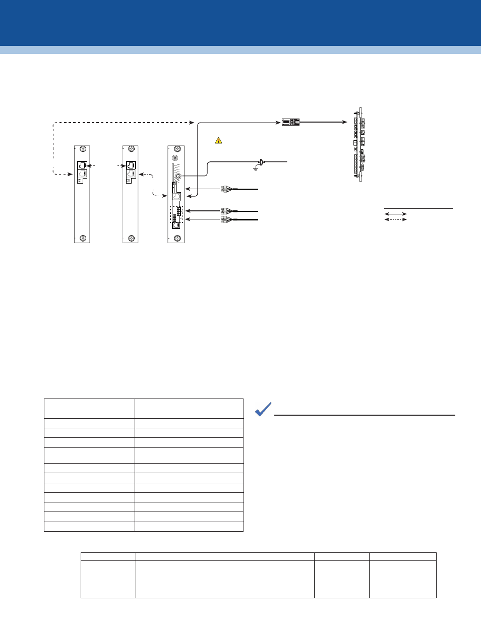
3. Make Battery Sense Wire Kit connections.
See the battery diagrams that came with the sense wire kit or reference the DSM2 Technical Manual.
4. Connect the RF drop and make front panel connections.
The DOCSIS specification for downstream power level is ± 15dBmV. However, for optimal performance, set the level as close to 0
dBmV as possible.
RF Cable to Headend
Required
Grounded Surge Protector
(Alpha P/N 162-028-10 or equivalent)
C
O
M
S
Y
S
C
O
M
S
Y
S
XM2
XM2
“Master”
XM2
Generator (ECM)
(Alpha p/n 744-726-XX)
ECM Technical Manual p/n 744-862-C0
ECM to SCM Interface
(Alpha P/N 704-709-20)
Battery String
Connectors
ALM
RDY
COM
LNK
RF
REG
DS
TMPR
CTRL
C
O
M
E
T
H
C
D
A
B
L
O
C
A
L
STAT
To Battery Sense Wire Harnesses
Environment Control Wire
(Alpha P/N 875-627-20) to Heater Mat, Fan, etc.
Serial Interface Card
(P/N 704-742-20)
System Port
Communications
Port
Communications
Port
Serial Interface Card
(P/N 704-742-20)
Connections
Connections with more
than one power supply
Legend:
Type SNAPSHOT, then press ENTER
Description
MAIN > SNAPSHOT
CM MAC 000308142452
MAC address of the cable modem
CPE MAC 0090EAA0F269
MAC address of the CPE Device
CM 192.168.1.204
IP address of the cable modem
CPE 192.168.1.205
IP address of the CPE device (dual IP mode
only)
BATT 1A-2A 13.4 13.4
Power supply battery voltages
BATT 3A-4A 13.7 --.-
Power supply battery voltages
CM TX (dBmV) 47.2
Cable modem transmit level
CM RX (dBmV) 8.5
Cable modem receive level
CM Ver 1.38
Cable modem firmware version
DSM VERV 2.02.1
Transponder processor firmware version
MAIN>
The procedure shown at left will allow you to see MAC
addresses, useful in working with network registration. IP
addresses can help determine if the transponder is recognized
by the management system, and if the transponder is in single
or dual IP operation (in dual IP, the CPE and CM will have an IP
address; in single, only the CM will have an IP address). Correct
battery voltages verify that the battery sense cable is connected
properly. Cable modem transmit and receive levels will be
helpful in verifying proper padding at the RF drop.
NOTE: