Alpha Technologies DSM2 User Manual
Power, Dsm2 hardware installation quick start guide
Power
DSM2 Hardware Installation Quick Start Guide
Configuring the network prior to installation is recommended to allow the transponder communication to be verified while
the technician is on-site eliminating the need for a second visit if there are any problems.
Hardware
Installation Procedure
1. Verify the power supply device address is correct.
Power supplies should be assigned a unique address, e.g.,1, 2, or 3 (do
not use 0). No two power supplies monitored by a single DSM2 can have
the same address. The address can be changed in the SETUP menu of
the power supply's smart display (Fig. 2). See the power supply's technical
manual for more information.
2. Install the DSM2.
a. Turn off the XM2 battery breaker and disconnect all inverter module
connections.
b. Loosen the inverter module thumb screws and slide the inverter module
out of the power supply just far enough to disconnect the ribbon cable.
Disconnect the ribbon cable and remove the inverter module. If the
inverter module is equipped with a communication module, remove it
by loosening the two Phillips captive screws "A" (Fig. 3).
c. Insert the 18-pin jumper into the Inverter Module (Fig. 4).
(For earlier versions, insert the longer pins into the inverter
module).
d. Line up the 18-pin jumper with the DSM2 connector and connect the
unit to the inverter module (Fig. 5).
e. Tighten the two captive screws to secure the DSM2, re-install the
inverter module, reconnect the ribbon cable, tighten thumb screws and
inverter module connections.
Inverter Module
Provision the RF MAC Address
The RF (modem) and CPE (Dual-IP) MAC Addresses are printed
on barcode labels on the front and side of the DSM2 (Fig.1), as
well as on the packing slip.
• Provision the RF MAC Address with the proper DOCSIS
®
configuration file.
• If operating in Dual IP Mode, provision the CPE MAC Address
so that it will be assigned a valid IP address on the public CPE
network through the modem.
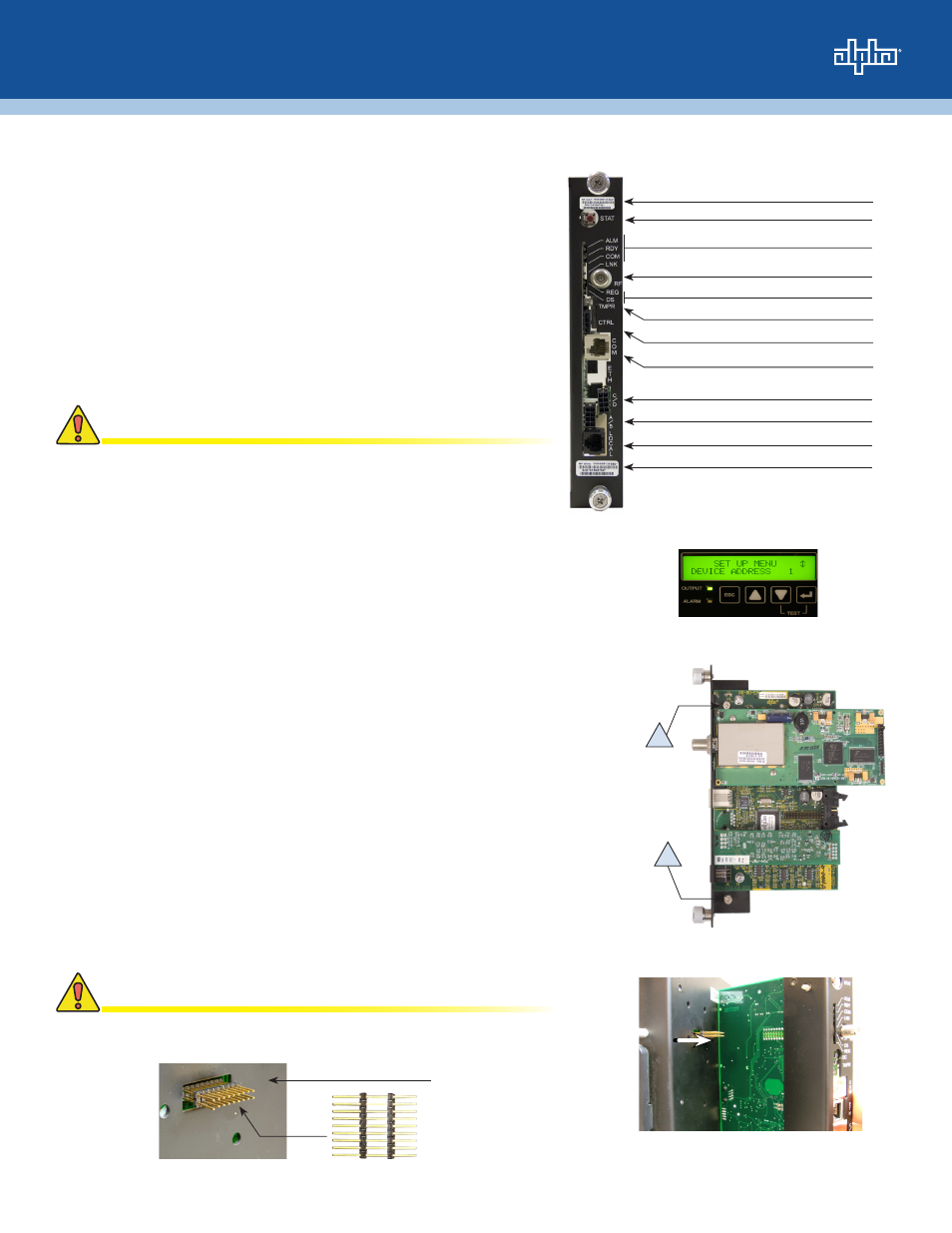
Reset Button
Status LEDs
RF Connection
Cable Modem Status LEDs
Tamper Switch Connection
AlphaBus Communication Port
Battery String Connection (C/D) (option)
Battery String Connection (A/B)
Local Port Connection
Modem's RF MAC Address
Environmental Control (option)
CPE MAC Address
Fig. 1, Front view with callouts
For units in service, backup battery power will not be available
during the following procedure.
CAUTION!
A
A
Fig. 2, Smart Display
Fig. 3, Captive Screw location
Fig. 4, 18-pin Jumper Installation Location
Fig. 5, Inverter Module, DSM2 connction
Verify the battery breaker remains in the OFF position.
CAUTION!