10 alarm and signal wiring connections for cxcm, Alarm and signal wiring connections for cxcm – Alpha Technologies Cordex 48-1kW 19 6000W Installation User Manual
Page 24
030-706-B2 Rev B
Page 16 of 26
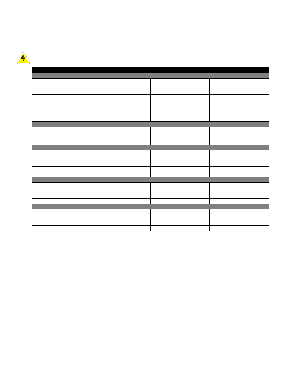
6.10 Alarm and Signal Wiring Connections for CXCM
For terminal block connections, the recommended wire sizes are 0.75 to 0.14mm
2
(#18 to #26 AWG) for the
temperature range of 0 to 50 deg. C (as per UL/CSA).
For insulation displacement receptacles, the recommended wire size is 0.75mm
2
(#18 AWG).
CAUTION: to reduce risk of fire, use only 0.129mm
2
(#26 AWG) or larger wire.
Terminal
Description
Signal Type
Range
Alarm Outputs –
Can be configured to de-energize on alarm (DOA) or energize on alarm (EOA).
#2-21,22(common)
K2, LVD2
NC/COM/NO (JP2)
60Vdc / 1A
#3-19,20(common)
K3, LVD3
NC/COM/NO (JP3)
60Vdc / 1A
#4-17,18(common)
K4, System Minor
NC/COM/NO (JP4)
60Vdc / 1A
#5-15,16(common)
K5, System Major
NC/COM/NO (JP5)
60Vdc / 1A
#6-13,14(common)
K6, AC Mains Hi-Low
NC/COM/NO (JP6)
60Vdc / 1A
#7-11,12(common)
K7, Not assigned
NC/COM/NO (JP7)
60Vdc / 1A
#8-9,10(common)
K8, Not assigned
NC/COM/NO (JP8)
60Vdc / 1A
#0-25,24,23
K0, System Fail Output*
NC/COM/NO
60Vdc / 1A
Digital Inputs –
See Table B for definitions of logic and system
P5-1,2
D1, Distribution Fuse (Alarm)
Pos (+) or Neg (-)
0—60Vdc
P5-3, P6-1
D2, Distribution CB (Alarm)
Pos (+) or Neg (-)
0—60Vdc
P6-2,3
D3, Battery CB (Alarm)
Pos (+) or Neg (-)
0—60Vdc
Analog Inputs and System Signals
E1
Battery -48V**
Neg (-)
20—60Vdc
J3
Ethernet port
N/A
N/A
P1-2,1
K1, LVD1
Pos (+) / Neg (-)
0—60Vdc / 1A
P7-2,1
V1, Load Voltage
Pos (+) / Neg (-)
0—100Vdc
P8-2,1
I1, Load Current
Pos (+) / Neg (-)
±50mV
–
for List 120, add the following:
1-2
T1 (GP1), Temp Probe 1
Pos (+) / Neg (-)
0—20Vdc
, with power source
3-4
T2 (GP2), Temp Probe 2
Pos (+) / Neg (-)
0—20Vdc
, with power source
5-6
GP3, General Input 3
Pos (+) / Neg (-)
Not used
7-8
GP4, General Input 4
Pos (+) / Neg (-)
±60V,
bi-polar voltage
–
for List 124, consult the factory to add the following:
1-2
V3 (GP1), Voltage Input 3
Pos (+) / Neg (-)
0—60Vdc
3-4
V4 (GP2), Voltage Input 4
Pos (+) / Neg (-)
0—60Vdc
5-6
V5 (GP3), Voltage Input 5
Pos (+) / Neg (-)
0—60Vdc
7-8
T1 (GP4), General Input 4
Pos (+) / Neg (-)
0—20Vdc
, with power source
Table B–Signal wiring connections for CXCM
*
System Fail output relay is fail-safe and will de-energize during an alarm condition.
**
Battery –48V: connect to battery only when using a battery disconnect device
NOTE: To aid the user with installation, frequent reference is made to drawings located at the rear of this manual.
Custom configurations may be detailed within the Apha power system documentation package.