Module installation and removal, Installing module, Removing module – Alpha Technologies SD08 User Manual
Page 15: 4 module installation and removal
Argus Technologies Ltd.
018-546-C0 Rev C WC
Printed in Canada. © 1999 Argus Technologies Ltd. ARGUS is a registered trademark of Argus Technologies Ltd. All Rights Reserved.
Page 7 of 11
5.4
Module Installation and Removal
WARNING: HIGH VOLTAGE AND SHOCK HAZARD.
Only qualified personnel familiar with line and battery voltage should attempt to change modules
while the SD08 Battery Fail Monitor cabinet is energized. Remove rings, watches and other jewelry
before performing this procedure. Keep fingers clear of live electric parts while unit is energized.
Leave cables disconnected at battery and verify polarity using a voltmeter. Make battery
connections only after all other wiring is completed.
5.4.1 Installing
Module
Battery sense leads should be bundled and routed through the rear of the module or rack per drawing 018-546-
08. Route through the side of the SD08 in the case of the stand-alone or wall mount unit. Insert each wire into the
appropriate terminal on the termination block and secure the wires by tightening the terminal screw. See
Specifications document located at the front of this manual for recommended wire sizes.
WARNING
Do not over tighten the terminal screws. This may result in damage to the input connectors.
The termination block can then be plugged into the SD08 module (cable routed through corresponding slot).
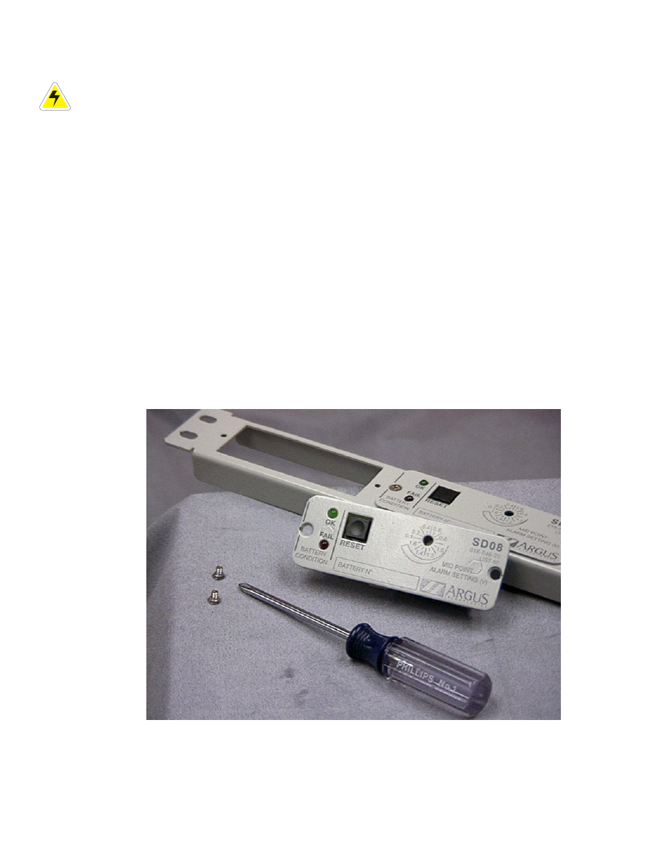
Attach the module to the panel with the screws provided (see Figure 4).
5.4.2 Removing
Module
Remove the two screws from the face of the module. Detach the module from the panel and unplug the cable
connector from the terminal block.
Figure 4–SD08 module, panel and mounting screws