Wiring and connections, Safety precautions, Grounding – Alpha Technologies SD08 User Manual
Page 14: Alarm connections, Latch, No latch (default), Iring and, Onnections, 5wiring and connections
Argus Technologies Ltd.
018-546-C0 Rev C WC
Printed in Canada. © 1999 Argus Technologies Ltd. ARGUS is a registered trademark of Argus Technologies Ltd. All Rights Reserved.
Page 6 of 11
5
Wiring and Connections
This chapter provides cabling details and notes on cable sizing for DC applications with respect to the product.
NOTE: Refer also to drawings located at the rear of this manual.
5.1 Safety
Precautions
WARNING
Hazardous voltages are present at both the input and the output of power systems. Ensure that
input power and output power is removed before attempting work on the CXC’s connections. Use
a voltmeter to verify the absence of voltage. Clearly mark the correct polarity of the battery leads
before commencing work on DC connections.
Refer to the previous (Installation) chapter for additional safety precautions.
5.2 Grounding
WARNING
For safety reasons, ensure the SD08 is properly bonded to the building’s ground grid.
5.3 Alarm
Connections
Alarm cables should be bundled and routed through the rear of the module or rack; through the side in the case of
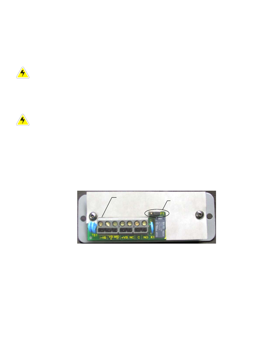
the stand-alone or wall mount unit. See drawing 018-546-08. Insert each wire into the appropriate terminal on the
termination block (see Figure 3) and secure the wires by tightening the terminal screw. See Specifications
document at the front of this manual for recommended wire sizes.
WARNING
Do not over tighten the terminal screws. This may result in damage to the input connectors.
The Fail Alarm terminals are connected to relay contacts in the SD08 module and both normally open or normally
closed contacts are provided. Latching is jumper selectable.
Figure 3–Rear view of SD08 module showing termination block
Wire #1
Jumper for alarm
(latch/no latch)
NOTE: The Fail Alarm relay is de-energized during alarm conditions.
5.3.1 Latch
Set the jumper (P1) to pins 1 and 2 for alarm “latch” (requires manual reset).
5.3.2
No Latch (default)
Set the jumper (P1) to pins 2 and 3 for alarm “no latch” (clears automatically).