English, Alarm in/out, Off half-duplex – ABUS TVCC81500 Quick Operating instructions User Manual
Page 42: Off yes, 1 circuit diagram
42
English
5.4 Simplex/half-duplex settings
Position 7 of the SW2 DIP switch is used for the communication setting.
SW2 DIP switch simplex/half-duplex settings
Description
Position 7 settings
7
Simplex
ON
1
2
3
4
5
6
7
8
SW2
OFF
Half-duplex
ON
1
2
3
4
5
6
7
8
SW2
ON
5.5 Terminating resistor setting
Position 8 of the SW2 DIP switch is used for the terminating resistor setting.
SW2 DIP switch terminating resistor settings
Description
Position 8 settings
8
No
ON
1
2
3
4
5
6
7
8
SW2
OFF
Yes
ON
1
2
3
4
5
6
7
8
SW2
ON
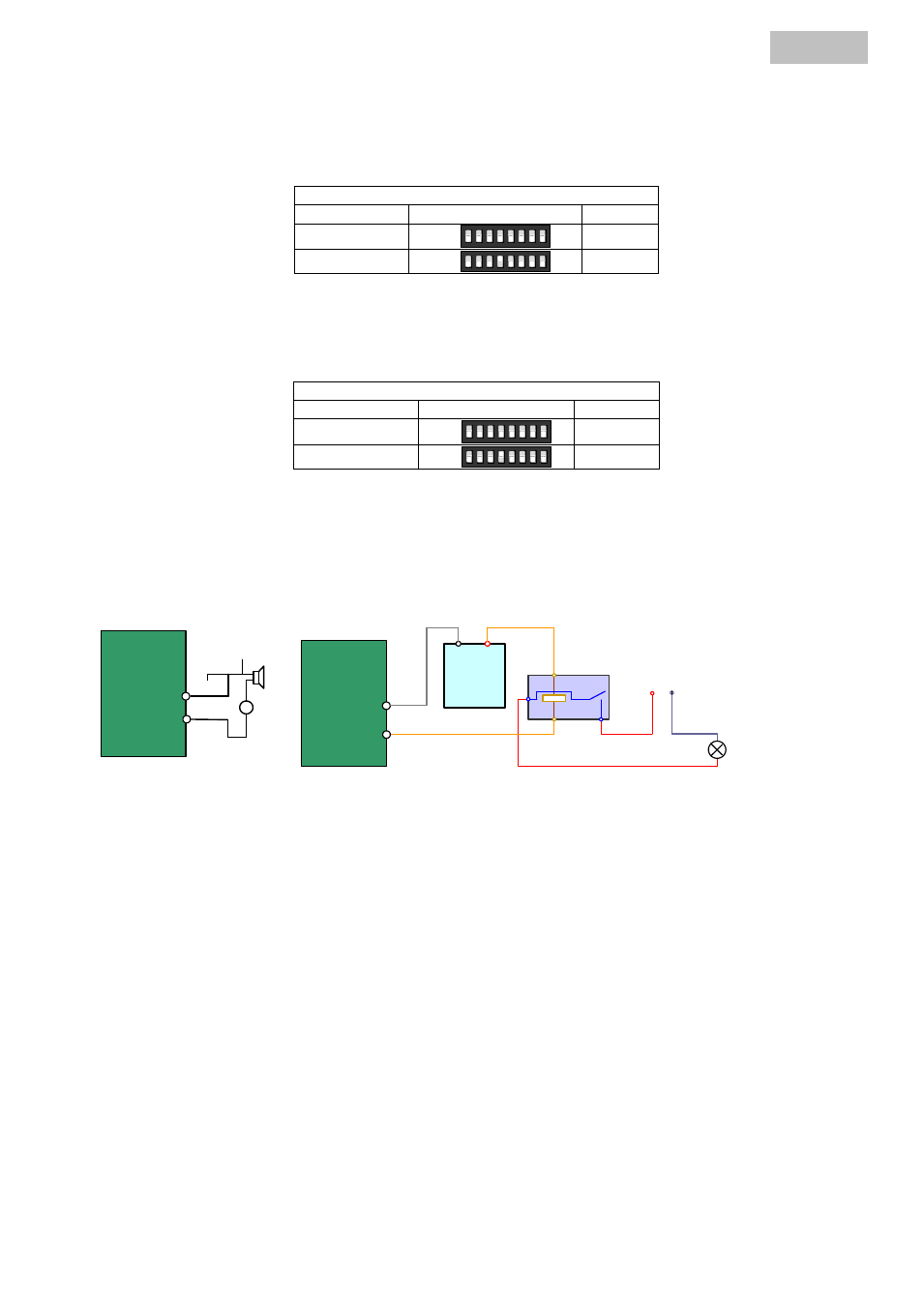
6. Alarm IN/OUT
6.1 Circuit diagram
JQC-3FG
Relay
12VDC
GND
OUT
L
N
~220V AC
Relay Output
Dome
(10 A 250VAC)
Diagram (left)
Diagram(right)
30mA
OUT(n)
OUT(n)
+
-
DC
DC Load
Relay Output
Dome
OUT(n)
OUT(n)
Circuit diagram left:
Consumers can be connected with the following load here.
DC: Max. 12 V DC, 30 mA
Schaltplan Right::
An external relay must be used to prevent electrical damage to the dome.