Elmo Rietschle L-BV5 Supplementary instructions User Manual
Page 6
Concerning 5 Installation
610.44440.40.200
6 / 12
© Gardner Denver Deutschland GmbH
b) Operating fluid temperature measurement in
the drain tapping (F2, Fig. 1, page 6), or on
the unit housing (F5, Fig. 1, page 6) with
suitable temperature sensor.
Disconnection condition:
Temperature ≥ 60 °C (140 °F)
The measurement and control device must be
suitable or certified to take reliable
measurements for disconnection conditions and
shut down the equipment if necessary.
The device must be certified with regard to its
point of installation in accordance with its
category.
It is recommendable to implement the monitoring
systems in accordance with EN ISO 13849.
The volume flow measurement sensor must be
suitable for the area prevailing in the measuring
point internal space.
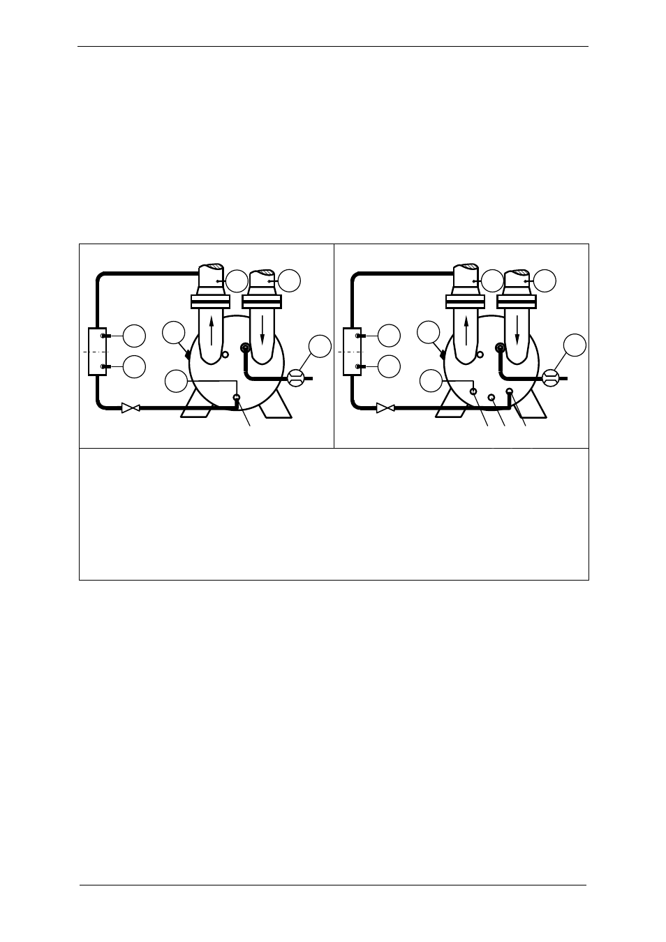
2BV2 0..
2BV5 1..
F1 Flow measurement in the operating fluid feed.
G1 Pressure measurement in propellant gas on
suction side, to monitor suction pressure
p
1
≤ p
vapour
+ 50 mbar
F2 Temperature measurement in the operating
fluid.
G2 Pressure measurement in propellant gas on
suction side as overload protection.
F3 Liquid level for operating liquid, maximum.
A Drain tapping
F4 Liquid level for operating liquid, minimum.
B,C Drain tapping (only 2BV5 1..)
F5 Temperature measurement on housing
Fig. 1: Position of measuring points
Monitoring liquid level before starting up
Monitoring the liquid level before starting up is
compulsory.
Monitoring can be ensured, for instance, by
inductive proximity switches, solenoid-operated
sensors, or pressure-dependent sensors, each
combined with an analysis device.
The liquid level switches (F3, F4, Fig. 1, page 6)
should be installed in the liquid level monitoring
device (position Fig. 1 page 6).
The monitoring device sensors must be non-
corrosive and certified for category 2 if there is
direct contact with the internal space.
The measurement and control device must be
suitable or certified to take reliable
measurements for disconnection conditions and
shut down the equipment if necessary.
The device must be certified with regard to its
point of installation in accordance with its
category.
It is recommendable to implement the monitoring
systems in accordance with EN ISO 13849.
The liquid level monitoring sensor must be
suitable for the area prevailing in the measuring
point internal space.
It must only be possible to turn on the unit if the
given fluid level stands between h
f min
and h
f max
(Fig. 2, page 7).
F2
F3
F4
F1
G1
G2
F5
B
C
A
F2
F3
F4
G1
F5
G2
F1
A