Gorman-Rupp Pumps SM4G1-X30 460/3 1002211 thru 1241783 User Manual
Page 17
OM−04417
SM SERIES
PAGE B − 12
INSTALLATION
connections. Make certain that the
pump and enclosure are properly
grounded; never use gas pipe as an
electrical ground. Be sure that the in-
coming power matches the voltage and
phase of the pump and control before
connecting the power source. Do not
run the pump if the voltage is not within
the limits.
Do not open the control box in an explo-
sive atmosphere. When sealed, the con-
trol box is explosion proof to prevent the
ignition of combustible gases. Opening
the box in an explosive atmosphere
could result in fire or explosion.
Field wiring is not provided with this pump, and
must be supplied by the user. The field wiring must
be of the proper size and type to ensure an ade-
quate voltage supply to the pump. Voltage avail-
able at the motor must be within the range indi-
cated in Table B-4.
To calculate the voltage available at the motor, pro-
ceed as follows:
a. Measure the incoming voltage across lines 1
& 2, 2 & 3, and 1 & 3 while the pump is oper-
ating at full capacity. See the wiring dia-
grams in this section for power supply con-
nections.
b. Next, subtract the motor cable voltage drop
(see Table B-5, Pump Power Cable Specifi-
cations).
c. Do not continue to operate the pump if this
voltage is not within the recommended limits.
Obtain the services of a qualified electrician to
determine the correct field wiring size and
other details to insure an adequate voltage
supply to the pump.
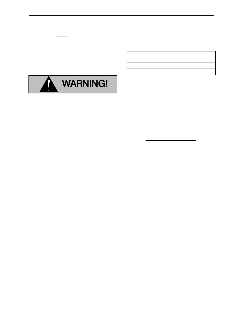
Table B-4. Pump Motor Voltage Limits
Nominal
Voltage
Phase
Minimum
Voltage
Maximum
Voltage
460
3
420
500
575
3
520
630
Use the packing gland nuts to secure and seal the
incoming field wiring to the control box. make cer-
tain all connections are tight and that cable entry
points are rainproof. Support the cable weight, if
required, to prevent excessive strain on cable
clamps and cable.
NOTE
After the power cables have been connected to the
control box, the packing gland nuts must be wired
and sealed before operation.
Grounding Methods
Electrically ground the installation before connect-
ing the field wiring to the control box. Install a
grounding terminal to the enclosure and connect it
to a properly embedded electrode.
The material used for the electrode must be an ex-
cellent conductor of electricity, such as copper. If
iron or steel is used, it must be galvanized or other-
wise metal plated to resist corrosion. Do not coat
the electrode with any material of poor conductiv-
ity, such as paint or plastic.
The electrode must conform to the recommenda-
tions of MSHA. Follow all installation requirements
of MSHA, and all applicable codes. See Figure B-2
for some suggested grounding methods.
- SM4G1-X30 575/3 1002211 thru 1241783 SM4J1-X60 460/3 1004954 thru 1241784 SM4C1-X10 460/3 1136140 and up SM4C1-X10 575/3 1136140 and up SM4C18-X10 460/3 1136140 and up SM4C18-X10 575/3 1136140 and up SM4C65-X10 460/3 915775 and up SM4C65-X10 575/3 915775 and up SM4D1-X10 460/3 1094445 and up SM4D1-X10 575/3 1094445 and up SM4D65-X10 575/3 915775 and up SM4D65-X10 460/3 915775 and up