Gorman-Rupp Pumps SM4G1-X30 460/3 1002211 thru 1241783 User Manual
Page 10
OM−04417
SM SERIES
PAGE B − 5
INSTALLATION
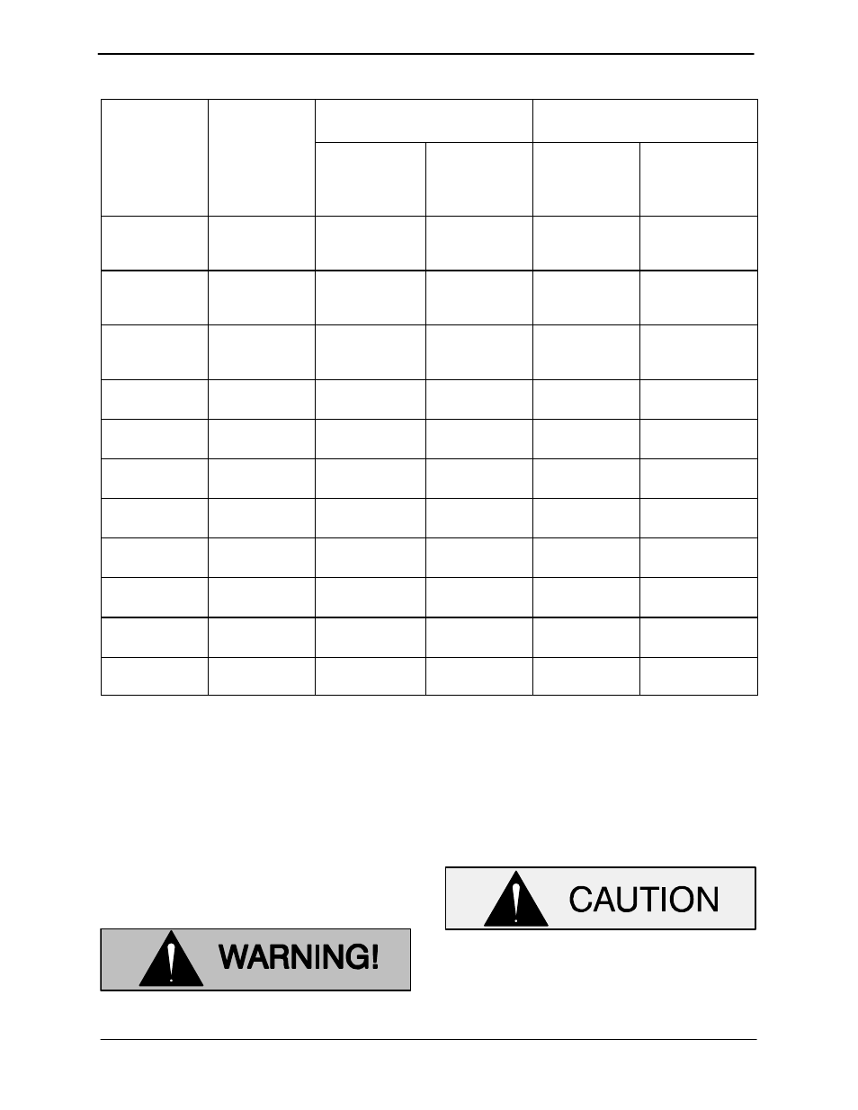
Table B-2. Additional Specifications (continued)
Pump
Model
Seal Cavity
Approximate Weight
Lbs. (kg)
Voltage/
Phase
Pump
Model
Filling Position
(H)orizontal
(V)ertical
Oil Capacity
Ounces
(Liters)
50Ft. Cable
Pump
Voltage/
Phase
SM3C1
SM3C18
SM3C65
460/3
575/3
106 (48)
109 (49)
205 (93)
23 (10,4)
16 (0,5)
H
SM4C1
SM4C18
SM4C65
460/3
575/3
183 (83)
188 (85)
303 (137)
23 (10)
20 (0,6)
H
SM4D1
SM4D18
SM4D65
460/3
575/3
173 (79)
173 (79)
281 (128)
23 (10)
20 (0,6)
H
SM4E1
460/3
575/3
302 (137)
38 (17)
32 (1)
H
SM4F1
460/3
575/3
302 (137)
38 (17)
32 (1)
H
SM4G1
460/3
575/3
541 (245)
38 (17)
112 (3,3)
V
SM4H1
460/3
575/3
183 (83)
23 (10)
20 (0,6)
H
SM4J1
460/3
575/3
774 (351)
53 (24)
144 (4,3)
V
SM4K1
460/3
575/3
253 (115)
23 (10)
32 (1)
H
SM6D1
460/3
575/3
538 (244)
38 (17)
112 (3,3)
V
SM6E1
460/3
575/3
765 (347)
53 (24)
144 (4,3)
V
Pump Dimensions
For the approximate physical dimensions of your
pump, refer to the pump specification data sheet or
contact your Gorman-Rupp distributor or the Gor-
man-Rupp Company.
PUMP INSTALLATION
When installing or servicing the pump
or controls, follow all requirements for
the installation of wiring or electrical
equipment as outlined in the National
Electric Code. Follow all MSHA safety
requirements. Failure to observe these
requirements could result in injury or
death to personnel.
Do not allow the free end of the power
cable to enter the liquid being pumped.
The free end of the cable must be kept dry
to prevent liquid from wicking through the
cable and into the motor.
- SM4G1-X30 575/3 1002211 thru 1241783 SM4J1-X60 460/3 1004954 thru 1241784 SM4C1-X10 460/3 1136140 and up SM4C1-X10 575/3 1136140 and up SM4C18-X10 460/3 1136140 and up SM4C18-X10 575/3 1136140 and up SM4C65-X10 460/3 915775 and up SM4C65-X10 575/3 915775 and up SM4D1-X10 460/3 1094445 and up SM4D1-X10 575/3 1094445 and up SM4D65-X10 575/3 915775 and up SM4D65-X10 460/3 915775 and up