Gorman-Rupp Pumps S8B1-E100 460/3 1432260 and up User Manual
Page 43
OM-06259
S SERIES PUMPS
PAGE E - 17
MAINTENANCE AND REPAIR
Heat the upper bearing (31) to a uniform tempera
ture no higher than 250
_F (120_C). Slide the bear
ing onto the shaft until it is fully seated against the
shaft shoulder. Do this quickly, in one continuous
motion, to prevent the bearing from cooling and
sticking on the shaft.
Use caution when handling hot bear
ings to prevent burns.
Clean the bearing cap (17) and position it over the
lower bearing (47) before heating.
NOTE
Position the cap on the bearing, so that when in
stalled on the shaft, the bearing will be positioned
as indicated in Figure E-4.
Heat the lower bearing and cap to a uniform tem
perature no higher than 250
_F (120_C). Slide the
assembled cap and bearing onto the shaft until the
bearing is fully seated against the shaft shoulder.
Do this quickly, in one continuous motion, to pre
vent the bearing from cooling and sticking on the
shaft.
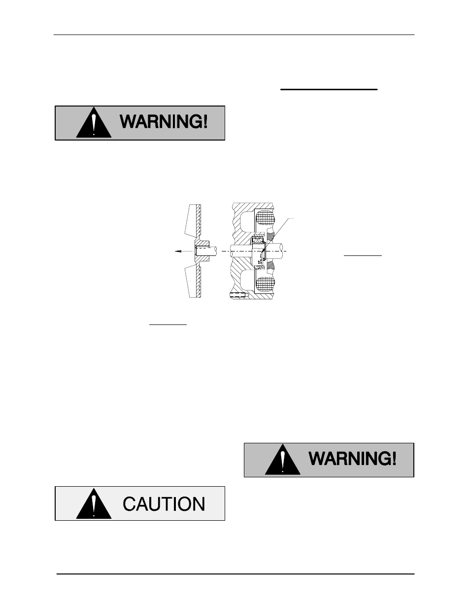
DIRECTION OF
THRUST
PART NUMBER MARKINGS ARE
LOCATED EITHER ON BEARING
O.D. (OFFSET FROM CENTER) OR
ON SIDE FACE OF BEARING. FOR
EITHER TYPE, POSITION BEAR
ING WITH TEXT AWAY FROM IM
PELLER.
INSTALLATION OF SKF 5200 AND 5300 SERIES BEARINGS
NOTE:
THIS BEARING IS MANUFACTURED WITH TWO SEALS OR SHIELDS. WHEN INSTALLED ON THE SHAFT, THE MAN
UFACTURER'S PART NUMBER DESCRIPTION (LOCATED ON SIDE FACE OF BEARING OR BEARING O.D.) MUST BE
LOCATED WITH THE TEXT AWAY FROM THE IMPELLER.
Figure E-4. Bearing Installation
After the bearings have been installed and allowed
to cool, check to ensure that they have not moved
out of position in shrinking. If movement has oc
curred, use a suitable sized sleeve and a press to
reposition the bearings. Make certain that they are
seated squarely against the shaft shoulders.
If heating the bearings is not practical, use a suit
able sized sleeve and an arbor (or hydraulic) press
to install the bearings on the shaft.
When installing the bearings onto the
shaft, never press or hit against the outer
race, balls, or ball cage. Press only on the
inner race.
Rotor Installation
(Figure E-1)
Use fresh solvent to clean all gasket and O‐ring
surfaces of the motor housing (18) and intermedi
ate (48), completely removing any old gasket and
cement material. Inspect the sealing surfaces for
burrs, nicks and pits which could cause a poor
seal. Repair or replace as require.
Most cleaning solvents are toxic and
flammable. Use them only in a well ven
tilated area free from excessive heat,
sparks, and flame. Read and follow all
precautions printed on solvent contain
ers.
Carefully ease the rotor (39), bearing cap (17) and
assembled bearings (31 and 47) into the interme