Gorman-Rupp Pumps 612L20-B 814882 and up User Manual
Page 28
OM−01395
60 SERIES
MAINTENANCE & REPAIR
PAGE E − 9
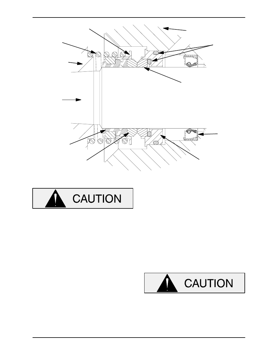
IMPELLER
SHAFT
SPRING
SEAL PLATE
RETAINER
OIL SEAL
BELLOWS
ROTATING
ELEMENT
STATIONARY
SEAT
IMPELLER
STATIONARY
ELEMENT
O-RINGS
Figure E−4. 12590B Seal Assembly
This seal is not designed for operation at
temperatures above 160
_F (71_C). Do not
use at higher operating temperatures.
Lay the seal plate on a flat surface with the impeller
side up. Press the oil seal (33) into the seal plate
with the lip positioned as shown in Figure E−1.
Press the stationary subassembly (consisting of
the stationary seat, O-rings and stationary ele-
ment) into the seal plate until fully seated.
Slide the seal plate onto the shaft and secure it to
the pedestal (29) with the round head machine
screws (12). Use caution not to damage the sta-
tionary portion of the seal on the shaft shoulders.
Slide the rotating subassembly (consisting of the
rotating element, retainer and bellows) onto the lu-
bricated shaft until the seal elements contact. In-
stall the seal spring.
Reinstall the air vent and piping (6, 7 and 8) and
bottle oiler and piping (9, 10 and 11). Lubricate the
seal assembly as indicated in LUBRICATION, af-
ter the impeller is installed.
Impeller Installation
Inspect the impeller, and replace it if cracked or
badly worn. If the wear ring (43) was removed, chill
the impeller by refrigeration and use an induction
heater or oven to heat the wear ring. Slide the wear
ring onto the impeller until fully seated against the
shoulder and allow it to cool.
The wear ring must seat squarely on the
impeller; otherwise binding and/or exces-
sive wear will occur. Use caution when han-
dling hot parts to prevent burns.
Install the woodruff key (50) and press the impeller
onto the shaft until fully seated.