Operation, cont’d, Example applications, Connecting audio outputs – Extron Electronics VTG 300_300R User Guide Rev. D User Manual
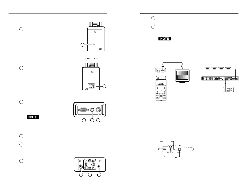
Page 9: Left side panel led (vtg 300r model only), Right side panel power input, Top panel video output, Bottom panel audio output
VTG 300/300R • Operation
VTG 300/300R • Operation
Operation, cont’d
2-5
2
Output 2: 3-pin XLR connector
— Balanced mono audio is
output from this male connector.
3
Output 3: 3.5 mm mini stereo phone jack
— Unbalanced mono
audio on both left and right channels is output from this female
mini phone jack.
See Connecting Audio Outputs in this chapter for
audio wiring instructions.
Example Applications
The following illustrations are examples of using the video and
audio testing features of the VTG.
AUDIO
3
2
1
RGB/Y,R-Y
,R-Y
S-VIDEO
COMPOSITE
VIDEO
VTG 300
VIDEO TEST GENERATOR
AUDIO
SIGNAL
TEST
PATTERNS
RANGE
OUTPUT RATE
RATE
MENU
NEXT
POWER
SELECT
LEVEL
FREQUENCY
VIDEO
P.NOISE
W. NOISE
SINE
SQUARE
POLARITY
SWEEP
CROSSHATCH
H. PATTERN
COLOR BARS
GRAYSCALE
ALT / MULTI
WHITE FIELD
PC
VIDEO
HDTV
16:9 HR
Extron
VTG 300
Video and Audio Test Generator
Front view
Top view
Bottom view
Extron 15 pin HD
VGA Cable
Extron
MLS 406MA
MediaLink
Switcher
RS-232/MLC/IR
INPUT 4
AUDIO INPUTS
LINE LEVEL
MONO
AUDIO
AUDIO
Tx Rx IR
12V
A
B C
LINEOUT
PREAMP
AUX/MIX
ADJUST
-42dB
TO
+24dB
L
R
L
R
L
R
1
2
3
INPUTS
OUTPUTS
VIDEO
H
V
B
G
R
Y
1
2
3
INPUTS
MONITOR OUT
4
5
6
C
100-240V
1.0A MAX.
50-60Hz
AMPLIFIED OUTPUT 20 WATTS MONO
DIRECT
XFMR
COM
4/8 ohm
100V
70V
70V Mono Distribution
Connecting Audio Outputs
The VTG has three types of audio output connectors: an RCA
jack, a 3-pin XLR connector, and a 3.5 mm mini stereo phone
jack.
Output 1
Unbalanced mono audio is output from this connector. Wire the
RCA connector as shown here.
Tip (+)
Sleeve ( )
2-4
Left Side Panel LED (VTG 300R
model only)
1
Battery charge status LED
— The
amber LED lights steadily when the
VTG is being charged, and blinks
steadily when the the VTG is fully
charged.
Right Side Panel Power Input
1
12 VDC power input
— The included
external 12 VDC, 100 VAC to 240 VAC,
50/60 Hz power supply plugs into this
connector located on the right side
panel.
Top Panel Video Output
1
RGB/R-Y, Y, B-Y output
— RGBHV,
RGBS, RGsB, RsGsBs, and
component video are output
through the 15-pin HD connector.
For NTSC/PAL rates, the
component video output
is intended for signal
verification and alignment, and should not be used as a
reference.
2
S-video output
— S-video is output through the 4-pin mini DIN
connector.
3
Composite video output
— Composite video is output through
the BNC connector.
Bottom Panel Audio Output
1
Output 1: RCA jack
—
Unbalanced mono audio is output
from this female jack.
AUDIO
3
2
1
2
1
3
Bottom panel
RGB/R-Y,Y,B-Y
S-VIDEO
COMPOSITE
VIDEO
1
2
3
Top panel
12 VDC
1A
Right side panel
1
CHARGE
S
TAT
U
S
Left side panel
1