Front panel features, Attention, On the diagram below) – Extron Electronics SW2 DP Setup Guide User Manual
Page 2: Power on the output display, Connect power to the switcher, Power on the source devices, Auto switch led, Input selection buttons, Signal status leds, Hdcp status leds
68-2245-50 Rev. A
06 12
2
© 2012 Extron Electronics All rights reserved.
Extron Headquarters
+800.633.9876 Inside USA/Canada Only
Extron USA - West
Extron USA - East
+1.714.491.1500 +1.919.850.1000
+1.714.491.1517 FAX
+1.919.850.1001 FAX
Extron Europe
+800.3987.6673
Inside Europe Only
+31.33.453.4040
+31.33.453.4050 FAX
Extron Asia
+800.7339.8766
Inside Asia Only
+65.6383.4400
+65.6383.4664 FAX
Extron Japan
+81.3.3511.7655
+81.3.3511.7656 FAX
Extron China
+4000.EXTRON
+4000.398766
Inside China Only
+86.21.3760.1568
+86.21.3760.1566 FAX
Extron
Middle East
+971.4.2991800
+971.4.2991880 FAX
Extron Korea
+82.2.3444.1571
+82.2.3444.1575 FAX
Extron India
1800.3070.3777
Inside India Only
+91-80-3055.3777
+91 80 3055 3737 FAX
12V
- - A MAX
PO
WER
EDID
ST
ORE
DEF
AUL
T
2
1
ST
ORED
RS-232
AUT
O
RX
G
TX
INPUTS
OUTPUT
EDID
REMO
TE
SW2 DP RS
6.
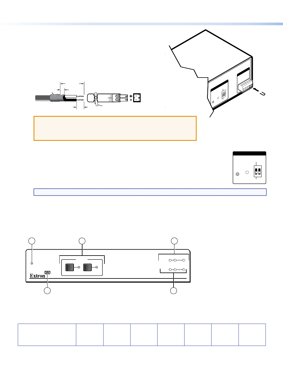
(Optional) Enable auto-input switching. Attach the 5-pole
captive screw plug to the Remote connector (
g
on the rear
panel diagram on the previous page) if this was not done in
step 5 for the RS-232 connection. Use a jumper wire to short pins 4
and 5 of the shared plug together (see the illustration at right).
When auto-input switching is in effect, the green Auto Switch LED
on the front panel lights (
a
on the diagram below).
7.
If necessary, wire a 2-pole captive screw connector (provided) to
your Extron power supply as shown below.
Captive Screw Connector
Tie Wrap
Heat
Shrink
1/8”
(3 mm)
7/8”
(22 mm)
3/16”
(5 mm) Max.
ATTENTION:
•
The power supply must not be permanently fixed to the
building structure or similar structures.
•
The power supply must not be located within environmental
air handling spaces or the wall cavity.
8.
Set the rear panel EDID DIP switch (switch 1, on the left) as follows:
•
Set the switch to Stored (down) if you want to store the EDID (resolution, refresh rate, and
clocking rate) of the connected display at the SW2 DP output (see the illustration at right), then
press the recessed EDID Store button. The EDID LED flashes amber, then lights steadily green
when the EDID has been stored.
•
Set the switch to Default (up) to select the Extron DisplayPort default EDID of 1920x1080 @
60 Hz with 2-channel audio.
NOTE: DIP switch 2 (on the right) is not functional.
9.
Power on the output display.
10.
Connect power to the switcher.
11.
Power on the source devices.
Front Panel Features
CONFIG
AUTO
SWITCH
SW2 DP
DISPLAYPORT SWITCHER
1
2
1
2
SIGNAL
INPUTS OUTPUT
HDCP
INPUTS
3
1
4
2
5
a
Auto Switch LED
b
Input Selection buttons
c
Signal Status LEDs
d
HDCP Status LEDs
e
USB Config port
EDID
STORE
DEFAULT
STORED
EDID