Audio input level adjustment, Twisted pair recommendations for dtp communication, Press the desired input button – Extron Electronics MPS 602 Series Setup Guide User Manual
Page 4: Do not exceed 40% fill capacity in conduits, Separate twisted pair cables from ac power cables
4
S
F
S
F
S
F
S
F
S
F
S
F
S
F
S
F
S
F
S
F
S
F
S
F
S
F
S
F
Front Panel LEDs
VGA Input
1
VGA Input
2
Input
1
Input
2
Input
3
Input
4
Input
5
Input
6
Ex
ec Mode
8
7
6
5
4
3
2
1
9
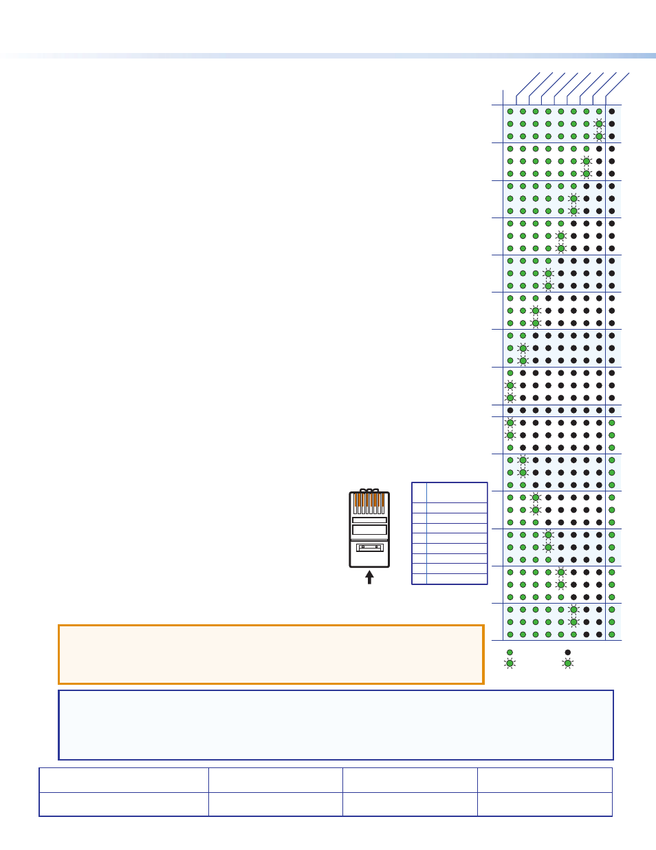
= on = off
= blinking fast = blinking slow
S
F
-10
-11
-12
-13
-14
-15
-16
-17
-18
+9
+8
+7
+6
+5
+4
+3
+2
+1
0
-1
-2
-3
-4
-5
-6
-7
-8
-9
+18
+17
+16
+15
+14
+13
+12
+11
+10
+24
+23
+22
+21
+20
+19
8
7
dB
6
5
4
3
2
1
9
k
Program Audio LEDs – Stacked LEDs indicate the program audio volume. No segments
lit indicate a volume level of 0 and all segments lit represent full volume (100). Segments in
between track volume levels between 0 to 100. The LEDs continue to display the current
volume level even when audio is muted (the red Mute LED lights).
l
Program Audio Volume Knob – Rotary encoder controls the line level program audio output
and the amplified audio output (MPS 602 SA and MPS 602 MA only). It has no effect on the
fixed audio output. Rotate the knob clockwise to increase and counterclockwise to decrease
the audio volume.
Audio Input Level Adjustment
Each analog audio input can be adjusted within a range of -18 dB to +24 dB. When adjusting the
audio level, the front panel LEDs used for RGB inputs 1 and 2 and Inputs 1 through 6 function as
indicators of the current audio level for the selected input as shown on the right.
Gain or attenuation is shown by the red Exec Mode LED: off indicates gain (+dB), on indicates
attenuation (-dB).
To adjust an audio input level from the front panel:
1.
Press and hold the Program Audio Mute and Mic Mute buttons for 3 seconds. The two mute
LEDs flash 3 times.
2.
Press the desired input button.
3.
Once the input button is selected, the front panel input LEDs indicate the current gain or
attenuation setting. By default, all inputs are set to 0 dB (all LEDs dark). Rotate the program
volume encoder clockwise to increase and counterclockwise to decrease the selected input
audio level. The front panel LEDs track the level as the knob is turned.
4.
Once the desired input level is set, the user can press the two mute buttons to exit, or within
3 seconds, select another input to adjust.
While in the input level adjustment mode, if a front panel button is not pressed or the program
knob is not rotated for more than 3 seconds, the switcher times out and exits the mode.
Extron Headquarters
+1.800.633.9876 (Inside USA/Canada Only)
Extron Asia
+65.6383.4400
Extron China
+86.21.3760.1568
Extron Korea
+82.2.3444.1571
Extron Europe
+31.33.453.4040
Extron Japan
+81.3.3511.7655
Extron Middle East
+971.4.299.1800
Extron India
+91.80.3055.3777
© 2013 Extron Electronics — All rights reserved. All trademarks mentioned are the property of their respective owners.
www.extron.com
68-2358-50
Rev. A
10 13
Twisted Pair Recommendations for DTP Communication
Extron recommends using the following practices to achieve full transmission distances up to 230
feet (70 m) and reduce transmission errors.
•
Use Extron XTP DTP 24 SF/UTP cable for the best
performance. If not using XTP DTP 24 cable, Extron
recommends 24 AWG, solid conductor, STP cable with a
minimum bandwidth of 400 MHz.
•
Terminate cables with shielded connectors to the TIA/EIA
T 568 B standard (shown to the right).
•
Limit the use of more than two pass-through points, which
may include patch points, punch down connectors, couplers,
and power injectors. If these pass-through points are
required, use CAT 6 or 6a shielded couplers and punch down
connectors.
ATTENTION:
•
Do not connect these devices to a computer or telecommunications network.
•
DTP remote power is intended for indoor use only. No part of the network that uses DTP
remote power should be routed outdoors.
NOTE: When using CAT 5e or CAT 6 cable in bundles or conduits:
•
Do not exceed 40% fill capacity in conduits.
•
Do not comb the cable for the first 20 m, where cables are straightened, aligned, and secured in tight bundles.
•
Loosely place cables and limit the use of tie wraps or hook and loop fasteners.
•
Separate twisted pair cables from AC power cables.
12345678
Insert Twisted
Pair Wires
Pins:
Pin
1
2
3
4
5
6
7
8
Wire color
T568B
White-orange
Orange
White-green
Blue
White-blue
Green
White-brown
Brown