Extron Electronics MDA 3 Series User Guide User Manual
Page 3
3
MDA 3 Series • User Guide
NOTES:
•
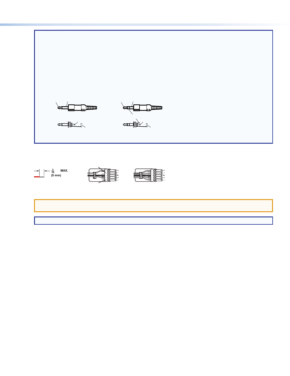
The length of exposed wires is critical. The ideal length is 3/16 inch (5 mm).
•
If the stripped section of wire is longer than 3/16 inch, the exposed wires may touch, causing a short circuit.
•
If the stripped section of wire is shorter than 3/16 inch, wires can be easily pulled out even if tightly fastened by
the captive screws.
•
Do not tin the power supply leads before installing them in the connector. Tinned wires are not as secure in the
connector and could be pulled out.
•
When making connections for the MDA from existing audio cables, see figure 3. A mono audio connector consists
of the tip and sleeve. A stereo audio connector consists of the tip, ring and sleeve. The ring, tip, and sleeve wires
are also shown on the captive screw audio connector diagrams, figure 2 and figure 4.
Tip (Left)
Sleeve (Gnd)
Tip (Left)
Ring (Right)
Sleeve (Gnd)
Tip
Sleeve
Unbalanced Mono
Unbalanced Stereo
Tip (Signal)
Sleeve (Gnd)
Figure 3.
Phono Audio Connectors
f
Audio Outputs (1 through 3) connectors — Connect up to three balanced or unbalanced audio devices to these 3.5 mm,
five-pole captive screw connectors. Connect audio devices, such as an audio amplifier or powered speakers. See figure 4 to
properly wire an output connector.
Unbalanced Stereo Output
Balanced Stereo Output
Do not tin the wires!
Tip
Ring
Tip
Ring
Sleeves
Tip
No Ground Here
No Ground Here
Tip
Sleeves
LR
LR
inch
Figure 4.
Captive Screw Connector Wiring for Audio Output
ATTENTION:
For unbalanced audio, connect the sleeves to the ground contact. DO NOT connect the sleeves to the
negative (-) contacts.
NOTE:
The length of exposed wires is important. The ideal length is 3/16 inch (5 mm) (see the
NOTES above for details).
g
Bal(anced)/Unbal(anced) DIP switches — For each balanced audio output, set the associated DIP switch to the Balanced
(up) position. For each unbalanced audio output, set the associated DIP switch to the Unbalanced (down) position.
The balanced or unbalanced nature of the audio output is determined by the output connector wiring, not the audio input.
Each output can be balanced or unbalanced independently of the other two outputs.