Connections, controls, and indicator, S-video (mda 3sv and mda 3sva), Figure 1. mda 3 series front and rear panels – Extron Electronics MDA 3 Series User Guide User Manual
Page 2: Input connectors, Out connector or outputs (1 through 3) connectors, Figure 2. captive screw input connector wiring
2
MDA 3 Series • User Guide
Connections, Controls, and Indicator
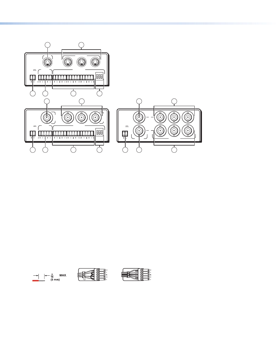
Figure 1 show all of the combinations of connectors that you may encounter with your MDA.
MDA 3AV
POWER
12V
.34A MAX
L
R
L
R
L
R
L
R
INPUT
OUTPUTS
1
2
3
BAL
1 2 3
UNBAL
1
I
N
O
U
T
2
3
MDA 3SVA
POWER
12V
.5A MAX
L
R
L
R
L
R
L
R
INPUT
OUTPUTS
1
2
3
BAL
1 2 3
UNBAL
1
2
3
INPUT
OUTPUTS
MDA 3V
DUAL
POWER
12V
.5A MAX
1
2
3
INPUT
OUTPUTS
1
2
3
A
B
MDA 3V Dual,
Rear Panel
MDA 3AV,
Rear Panel
MDA 3SVA,
Rear Panel
1
2
3
4
3
4
5
8
6
7
5
3
8
8
6
4
7
Figure 1.
MDA 3 Series Front and Rear Panels
S-video (MDA 3SV and MDA 3SVA)
a
Input connectors —
Connect an S-video input to this four-pin mini DIN connector.
b
Out connector or Outputs (1 through 3) connectors —
Connect up to three S-video devices to these four-pin mini DIN
connectors.
Composite Video (MDA 3V, MDA 3AV, and MDA 3V Dual)
c
In connector or Input connector — Connect a composite video input to this BNC connector. On the Dual model, Input A and
Input B are completely separate inputs to two separate distribution amplifiers.
d
Out connector or Outputs (1 through 3) connectors — Connect up to three composite video devices to these BNC
connectors. On the Dual model, the A output signals are identical to the A input, and the B output signals are identical to the B
input.
Audio on captive screw connectors (MDA 3AV, MDA 3SVA, MDA 3A)
e
Audio Input connector — Connect a balanced or unbalanced audio input to this 3.5 mm, five-pole captive screw connector.
Connectors are included, but you must supply the audio cable. See figure 2 to wire a connector for the appropriate input type
and impedance level. High impedance is generally over 800 ohms.
Unbalanced Stereo Input
Balanced Stereo Input
Do not tin the wires!
Tip
Ring
Tip
Ring
Sleeves
Tip
Sleeve
Sleeve
Tip
LR
LR
inch
Figure 2.
Captive Screw Input Connector Wiring