Installation, Specifications, Connections and indicator – Extron Electronics MDA 5SV User’s Manual Rev. B User Manual
Page 4
○
○
○
○○○○○○○○○○○○○○○○○○○○○○○○○○○○○○○○○○○○○○○○○○○○○○○○○○○○○○○○○○○○○○○○○○○○○○○○○○○○○○○○○○○○○○○○○○○○○○○○○○○○○○○○○○○○○○○○○○○○○○○○○○○○
○○○○○○○○○○○○○○○○○○○○○○○○○○○○
○
○
○
○
○
○
○
○
○
○
○
○
○
○
○
○
○
○
○
○
○
○
○
○
○
○
○
○
○
○
○
○
○
○
○
○
○
○
○
○
○
○
○
○
○
○
○
○
○
○
○
○
○
○
○
○
○
○
○
○
○
○
○
○
○
○
○
○
○
○
○
○
○
○
○
○
○
○
○
○
○
○
○
○
○
○
○
○
○
○
○
○
○
○
○
○
○
○
○
MDA 5V, 5SV, 5A RCA • Specifications
MDA 5V, 5SV, 5A RCA • Connections
Installation
5
4
MDA 5V, 5SV, 5A RCA • Specifications
MDA 5V, 5SV, 5A RCA • Specifications
Specifications
7
6
2
.
If feet were previously installed on the bottom of the MDA,
remove them.
3
.
For furniture mounting,
hold the MDA with the attached
brackets against the underside of the table or other
furniture. Mark the location of the screw holes of the
bracket on the mounting surface.
4
.
For furniture mounting,
drill 3/32” (2 mm) diameter pilot
holes, 1/4” (6.3 mm) deep in the mounting surface at the
marked screw locations.
5
.
For furniture mounting,
insert #8 wood screws into the four
pilot holes. Tighten each screw into the mounting surface
until just less than 1/4” of the screw head protrudes.
6
.
For furniture mounting,
align the mounting screws with
the slots in the brackets and place the MDA against the
surface, with the screws through the bracket slots.
7
.
For furniture mounting,
slide the receiver slightly forward
or back, then tighten all four screws to secure the MDA in
place.
8
.
For projector mounting,
secure the MDA to a projector
mount or other surface by inserting the mounting bolt
through the bracket’s slotted hole.
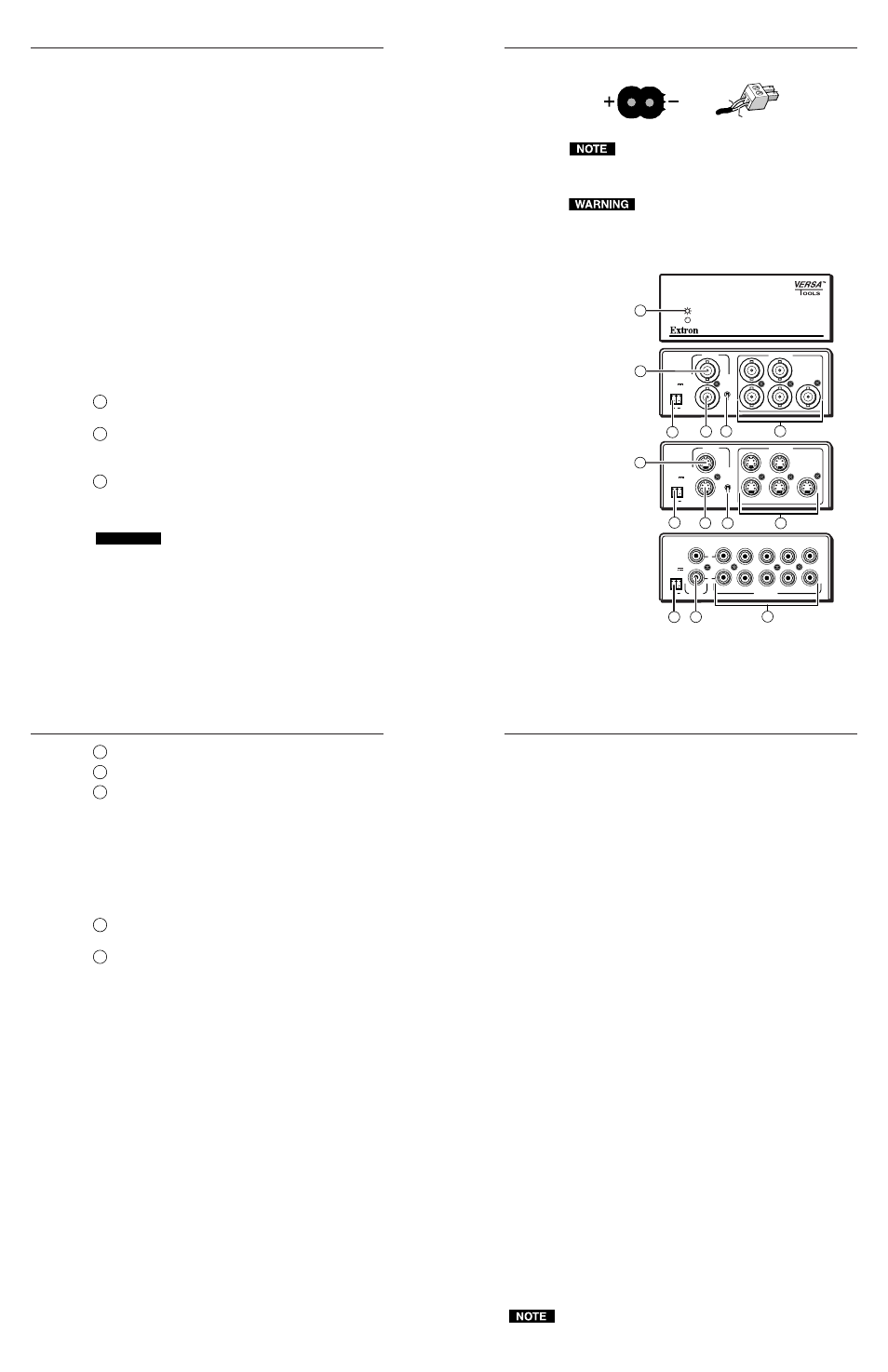
Connections and Indicator
Refer to figure 5.
1
Video Input connector
— (MDA 5V - composite video and
MDA 5SV - S-video) Connect an input to this connector.
2
Video Outputs (1 through 5) connectors
— Connect up to
five video devices to these connectors. (MDA 5V -
composite video and MDA 5SV - S-video).
3
Power connector—
Plug the external 12V power supply
into this 2-pole captive screw connector. The power supply
is included with the unit. Figure 4 shows how to wire the
connector.
CAUTION
When connecting the power supply, voltage polarity
is extremely important. Applying power with
incorrect voltage polarity could damage the power
supply and the MDA. Identify the power cord
negative lead by the ridges on the side of the cord.
Figure 4 — Power connector wiring
Do not tin the stripped power supply leads before
installing the captive screw connector. Tinned wires are
not as secure in the captive screw connectors and could
pull out.
The two power cord wires must be kept separate
while the power supply is plugged in. Remove
power before continuing.
To verify the polarity before connection, plug in the power
supply with no load and check the output with a voltmeter.
Figure 5 — MDA 5V front and rear panels
4
Power LED —
Indicates power is applied.
5
Loop connector
— Provides passive loop-through for signal
6
High Z / 75 Ohm switch
— Select 75-ohm termination on
or off.
High Z
— Select this position (up) if you are
connecting a terminated device to the Loop connector.
75 Ohm
— This position (down) terminates the Input
connector with 75 ohms of impedance. Select this
position if you are not using the Loop connector, or if
you are connecting an unterminated device to the
Loop connector.
7
Audio input (left and right) connectors
— Connect
unbalanced stereo to this RCA connector
8
Audio output
(1 through 5, left and right) connectors —
Connect up to five audio (stereo) devices to these RCA
connectors.
Specifications
Video
Gain ................................................... Unity
Bandwidth
MDA 5SV ............................. 270 MHz (-3dB)
MDA 5V ............................... 435 MHz (-3dB)
Differential phase error .................. 0.05º, 0 to 50 MHz
Differential gain error .................... <0.05%, 0 to 50 MHz
Video input
Number/signal type
MDA 5SV ............................. 1 NTSC/PAL/SECAM S-video
MDA 5V ............................... 1 NTSC/PAL/SECAM composite video
Connectors
MDA 5SV ............................. 1 4-pin mini DIN female
MDA 5V ............................... 1 BNC female
Nominal levels ................................. Composite video and Y of S-video: 1V p-p
C of S-video: 0.3V p-p
Minimum/maximum level(s)
MDA 5SV ............................. Y: 0.4V to 2.0V p-p with no offset
MDA 5V ............................... 0.4V to 2.0V p-p with no offset
Impedance ........................................ 75 ohms
Return loss ........................................ <-40dB @ 0 to 10 MHz for MDA 5V
<-25dB @ 0 to 10 MHz for MDA 5SV
Maximum DC offset ....................... 1.0V
Video output
Number/signal type
MDA 5SV ............................. 6 S-video: 5 buffered for distribution, 1
passive loop-through
MDA 5V ............................... 6 composite video: 5 buffered for
distribution, 1 passive loop-through
Connectors
MDA 5SV ............................. 6 4-pin mini-DIN
MDA 5V ............................... 6 BNC female
Nominal levels ................................. Composite video and Y of S-video: 1V p-p
C of S-video: 0.3V p-p
Minimum/maximum level(s) ....... 0.4V to 2.0V p-p
Impedance ........................................ 75 ohms
Return loss ........................................ -30dB @ 5 MHz
DC offset ........................................... ±5mV maximum with input at 0 offset
Sync
Standards .......................................... NTSC 3.58, NTSC 4.43, PAL, SECAM
Audio — MDA 5A RCA
Gain ................................................... Unity (0dB)
Frequency response ........................ 20 Hz to 20 kHz, ±0.05dB
THD + Noise .................................... 0.03% @ 1 kHz at nominal level
S/N .................................................... >90 dB, at rated maximum output drive
Stereo channel separation .............. >80 dB @ 1 kHz; >60 dB @ 20 kHz
CMRR ................................................ >75 dB @ 20 Hz to 20 kHz
Audio input — MDA 5A RCA
Number/signal type ...................... 1 stereo unbalanced
Connectors ....................................... 2 RCA connectors
Impedance ........................................ >10 kohms unbalanced, DC coupled
Nominal levels ................................. Compatible with -10dBV (316mV), +4dBu
(1.23V), 0dBu (0.775V), -20dBV (100mV)
Maximum level ............................... +18 dBu unbalanced at 1%THD+N
Audio output — MDA 5A RCA
Number/signal type ...................... 5 stereo, unbalanced
Connectors ....................................... 10 RCA connectors
Impedance ........................................ 50 ohms unbalanced
Gain error ......................................... ±0.1dB channel to channel
Nominal levels ................................. Compatible with -10dBV (316mV), +4dBu
(1.23V), 0dBu (0.775V), -20dBV (100mV)
Maximum level (Hi-Z) ................... >+18dBu, unbalanced at 1%THD+N
0dBu = 0.775 volts (RMS).
Return
+12V
End view of power
supply output cord.
Captive Screw
Connector
DISTRIBUTION AMPLIFIER
MDA 5SV
POWER
12V
.5A MAX
4
3
5
INPUT
IN
HIGH Z
75 Ohm
LOOP
2
1
OUTPUTS
5
2
1
6
MDA 5V
POWER
12V
.5A MAX
4
3
5
INPUT
IN
HIGH Z
75 Ohm
LOOP
2
1
OUTPUTS
1
2
3
5
6
MDA 5A RCA
POWER
12V
.34A MAX
INPUT
OUTPUTS
1
2
3
4
5
L
R
7
8
3
3
Front Panel
All Models
Rear Panel
MDA 5V
Rear Panel
MDA 5SV
Rear Panel
MDA 5A RCA
4