Appendix a, Specifications, part numbers, and accessories, Irl 20 – Extron Electronics IRL 20 User Manual
Page 9: Installation and operation, cont’d
IRL 20 • Installation and Operation
Installation and Operation, cont’d
IRL 20
A
Appendix A
Specifications, Part Numbers,
and Accessories
Specifications
Included Parts
Accessories
Cables
2-6
2.
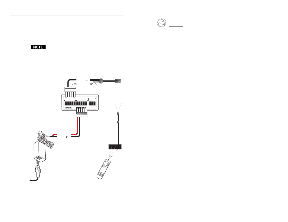
Attach the black wire of an Extron IR Emitter to pin B
(ground) and the white striped wire to pin D (IR signal) of
a 3.5 mm captive screw connector, and plug it into the
IRL 20’s remaining communications connector, as shown
below. Two or three emitters can be wired to the same
connector, if needed.
You can use one 5-pole connector to connect both the
power input and the IR Emitter (IR output). It is not
necessary to use two connectors.
3.
Place the head of the IR Emitter near or in front of the IR
pickup device of the IR-controllable Extron product.
+
12V
G
N
D
C
M
M
od
IR
SCP
+
1
2V
G
N
D
C
M
M
od
IR
SCP
IR SNSR
IRL 20
GND
SIG
+5V
IRL 20
Rear
External
power supply
(12 VDC, 1 A max.)
B
A
Stand-alone IRL 20 with power supply and IR Emitter
+12 VDC
Ground ( )
B
A
Modulated IR
Ground ( )
IR
Emitter
White Striped
Wire Only
IRL 20
To an
IR-Controlled
Extron
Device
Extron
IR Remote