Extron Electronics IRL 20 User Manual
Page 4
IRL 20 • Quick Start Guide
Quick Start Guide — IRL 20, cont’d
IRL 20 • Table of Contents
Table of Contents
68-1036-01 Rev. A
12 04
All trademarks mentioned in this manual are the properties of their respective owners.
Chapter 1 • Introduction
.......................................................... 1-1
About the IRL 20
.................................................................... 1-2
Features
...................................................................................... 1-2
Chapter 2 • Installation and Operation
......................... 2-1
UL Requirements
.................................................................... 2-2
Front and Rear Panel Features
....................................... 2-2
Connecting an IRL 20 to a MediaLink switcher or
controller, an AVT 100, or another Extron product ............ 2-4
Connecting an IRL 20 to a power supply
and an IR Emitter ................................................................... 2-5
Appendix A • Specifications
,
Part Numbers,
and Accessories
.............................................................................. A-1
Specifications
......................................................................... A-2
Included Parts
......................................................................... A-3
Accessories
............................................................................... A-3
Cables
......................................................................................... A-3
i
QS-2
communications connector. If desired, terminate the other end of the
cable and plug it into a communications connector on an optional
control module.
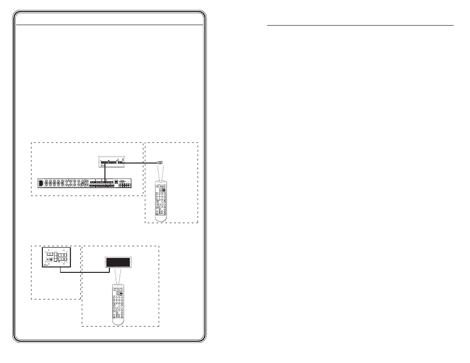
Step 7
Verify correct wiring and cabling, and test the system: connect the
devices to a power source, turn them on, aim an IR remote control at
the IRL 20, and check for the appropriate response at the remotely
controlled Extron device.
Step 8
If needed, disconnect all the devices from the power source(s), and
correct any cabling errors.
Step 9
Restore power to the equipment.
100-240V 1.3A
50-60Hz
+
_
LEFT
+
RIGHT
_
2
1
C
C
4
3
C
6
5
C
Tx Rx G
G
S G
S
G
S G
S G
G
Ps
+V
+V
CM IR SCP
R
Y/C
G
Y
B
V
H
VID
Y/C
VID
C
Y
R/VID
G/Y
B/C
H
V
C
VID
V
H
R/VID
G/Y
B/C
INPUT 1
INPUT 3
INPUT 4
INPUT 2
R
CM/IR/SCP
RS-232
2
PROJ CONT
A
U
DIO
RELAYS
IR/SERIAL OUT
E
C
B
B
D
A
A
L LINEOUT R
L PREAMP R
L 1 R
L 2 R
AMPLIFIED
OUT
4/8 ohm
CONFIG/RS-232
LAN
OUTPUT
A
L 3 R
L 4 R
B
C
D
+
1
2
V
G
N
D
C
M
M
od
IR
S
C
P
+
1
2
V
G
N
D
C
M
M
od
IR
S
C
P
IR SNSR
IRL 20
GND
SIG
+5V
Extron
IR Sensor
Extron
IR 402 Remote
Extron
System 5 IP
Equipment Room
Meeting Room
Extron
IRL 20
Extron
IR 402 Remote
Equipment Room
Meeting Room
Extron
IRL 20
Extron
MLC 226
PROJECTOR
MLC 226 IP
1
2
3
4
5
6
VOLUME
CONFIG
IR
ON
OFF
LIGHT
ON
LIGHT
OFF
LAPTOP
VCR
DVD
PC
AUX
VIDEO
LECTERN
PC
AUTO
IMAGE