Installation – Extron Electronics IN3214 User Manual
Page 3
IN3212 and IN3214 • Furniture Mounting
5
IN3212 and IN3214 • Jumper Configuration
Installation
4
3
.
Place the DA in the desired location or mount it in a convenient
location using the optional mounting brackets.
4
.
Connect the input device(s) to the input connector(s).
5
.
Connect the output devices to the output connectors.
CAUTION
Ensure you are using the correct power supply, 110V
or 220V, for your region. Using the wrong power
supply will damage the DA.
6
.
Apply power to all devices and turn on the input and
output devices.
7
.
Adjust the gain and peaking as needed. See Connections and
Controls.
Jumper configuration
The DA is factory configured in normal mode (IN3214 only) with
the Loop Out/Input 2 connector terminated (no loop-through).
For any other type of video, reconfigure the jumpers as follows:
1
.
Remove the screw on each side of the cover (figure 3).
OU
TP
UT
LO
OP
O
UT
/
IN
PU
T 2
OU
TP
UT
1
OU
TP
UT
2
OU
TP
UT
3
OU
TP
UT
4
IN
PU
T
1-IN 4-OUT VIDEO DISTRIBUTION
AMPLIFIER / LINE DRIVER
32
14
TM
Remove screw
each side.
Remove the four
hex nuts.
Figure 3 — Opening the DA
2
.
Using an Extron BNC extraction tool (part #100-096-01) or a
14mm, deep well socket, remove the four hex nuts securing
the output BNC connectors to the rear panel. Slide the
cover forward until the cover clears the BNC connectors.
Lift the cover off.
3
.
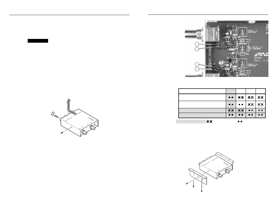
Locate J2 through J5 on the printed circuit board (figure 4).
4
.
Set the jumpers as shown in the table on the following page.
5
.
Replace the cover and reinstall the screws.
J3
J2
J4
J5
Figure 4 — Jumper locations
Normal/75 ohms (default)
No loop-through on input 2.
Normal/High Z
Loop-through on input 2.
Split/75 ohms
Split/High Z
Shaded = IN3214 only, = jumper installed, = jumper removed.
Mode/Termination
J5
J3
J4
J2
Furniture mounting
If desired, furniture mount the unit using the optional IN9127
mounting brackets, as follows:
1
.
Attach the mounting brackets to the distribution amplifier
with the provided machine screws (figure 5).
OU
TP
UT
LO
OP
O
UT
/
IN
PU
T 2
OU
TP
UT
1
OU
TP
UT
2
OU
TP
UT
3
OU
TP
UT
4
IN
PU
T
1-I
N
4-O
UT
V
ID
EO
D
IS
TR
IB
UT
IO
N
AM
PL
IF
IE
R
/ L
IN
E
DR
IV
ER
32
14
TM
Figure 5 — Desk mounting the IN3212 and IN3214