Installation, Introduction, Features – Extron Electronics IN3214 User Manual
Page 2: Normal and split mode (in3214 only)
IN3212 and IN3214 • Installation
3
IN3212 and IN3214 • Normal and Split Mode (IN3214 Only)
Installation
2
Introduction
The IN3212
™
and IN3214
™
are high performance composite video
or (for IN3214 only) S-video distribution amplifiers with gain and
peaking controls. The IN3212 features 300 MHz (-3dB)
bandwidth and the IN3214 features 280 MHz (-3dB) bandwidth.
The compact design allows them to be installed in any convenient
location. They accept NTSC, PAL, and SECAM video signals, as
well as high resolution monochrome, and distribute the signal to
separately buffered outputs.
Both models are powered by an external 110V or 220V power
supply. The power supply included with each unit is appropriate
to the region where the DA is sold.
Features
• Two (IN3212) or four (IN3214) outputs —
Distribute a video
signal from a single input to two or four outputs.
• Gain and Peaking controls —
Compensate for long cable runs
and increase fine details and clarity.
• Quad-standard compatibility —
Compatible with composite
NTSC 3.58, NTSC 4.43, PAL, and SECAM video as well as high
resolution monochrome video signals.
• Split mode operation (IN3214) —
Can be functionally split
into two independent two-output distribution amplifiers.
• Local monitor loop-through —
Provides a passive loop-
through signal for a local monitor, or to create a larger DA
system.
Normal and Split Mode (IN3214 Only)
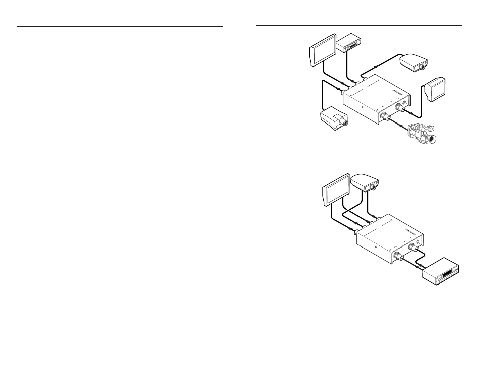
The IN3214 can be configured to either normal mode or split mode.
• Normal mode (factory default) — A single 1-input by 4-output
composite video distribution amplifier (figure 1).
In this mode, the Loop Out/Input 2 connector can be jumpered
as a loop-through to provide a buffered local output signal.
• Split mode — Two, independent 1-input by 2-output DAs.
Composite video —
The DA can accept two composite video
inputs and distribute eachinput to two separate outputs.
If a loop-through signal is required when the IN3214 is
configured for split mode and is buffering composite video, set
the inputs for High Z (see the jumper table on page 5) and use
a BNC “T” connector on the input to split the signal.
S-video —
The DA can accept a single S-video input (with the
luminance [Y] input on one input connector and the
chrominance [C] input on the other) and distribute the Y/C
output to two separate S-video devices (figure 2).
Projector
Monitor
VCR
HDTV
Plasma
Video Camera
LCD Projector
OU
TP
UT
LO
OP
O
UT
/
IN
PU
T 2
OU
TP
UT
1
OU
TP
UT
2
OU
TP
UT
3
OU
TP
UT
4
IN
PU
T
1-I
N
4-O
UT
V
ID
EO
D
IS
TR
IB
UT
IO
N
AM
PL
IF
IE
R
/ L
IN
E
DR
IV
ER
32
14
TM
Extron
IN3214
Video Distribution
Amplifier
Figure 1 — Typical normal mode composite video
application
HDTV
Plasma
DVD
Y
C
Y
Y
C
C
LCD
Projector
OUTPUT
LOOP OUT/
IN
PUT 2
OUTPUT 1
OUTPUT 2
OUTPUT 3
OUTPUT 4
INPUT
1-IN
4-O
UT
V
ID
EO
D
IS
TR
IB
UT
IO
N
AM
PL
IFIE
R / L
IN
E D
RIV
ER
3214
TM
Extron
IN3214
Video Distribution
Amplifier
Figure 2 — Typical split mode S-video application
Installation
1
.
Turn off and disconnect all equipment.
2
.
If necessary, reconfigure the internal jumpers for the desired
mode and Loop Out/Input 2 connector termination. See Normal
and Split Mode (IN3214 Only) and Jumper configuration.