Extron Electronics IN3556 User Manual
Page 8
4
IN3554 / IN3556 OPERATION MANUAL - REV. 2.1 02/19/00
©1996-1997 - INLINE, INC.
Tally Output
The REMOTE CONTROL port also provides tally outputs (pins 10 - 15) which may be used to trigger
other devices, provide feedback to a control system, or light indicator lights on a custom remote control
panel. When a channel is selected, either from the front panel or through the REMOTE CONTROL port,
the Tally Output for that channel is switched on. The Tally Output can switch voltages of up to 50 volts
and current up to 1.5 amps.
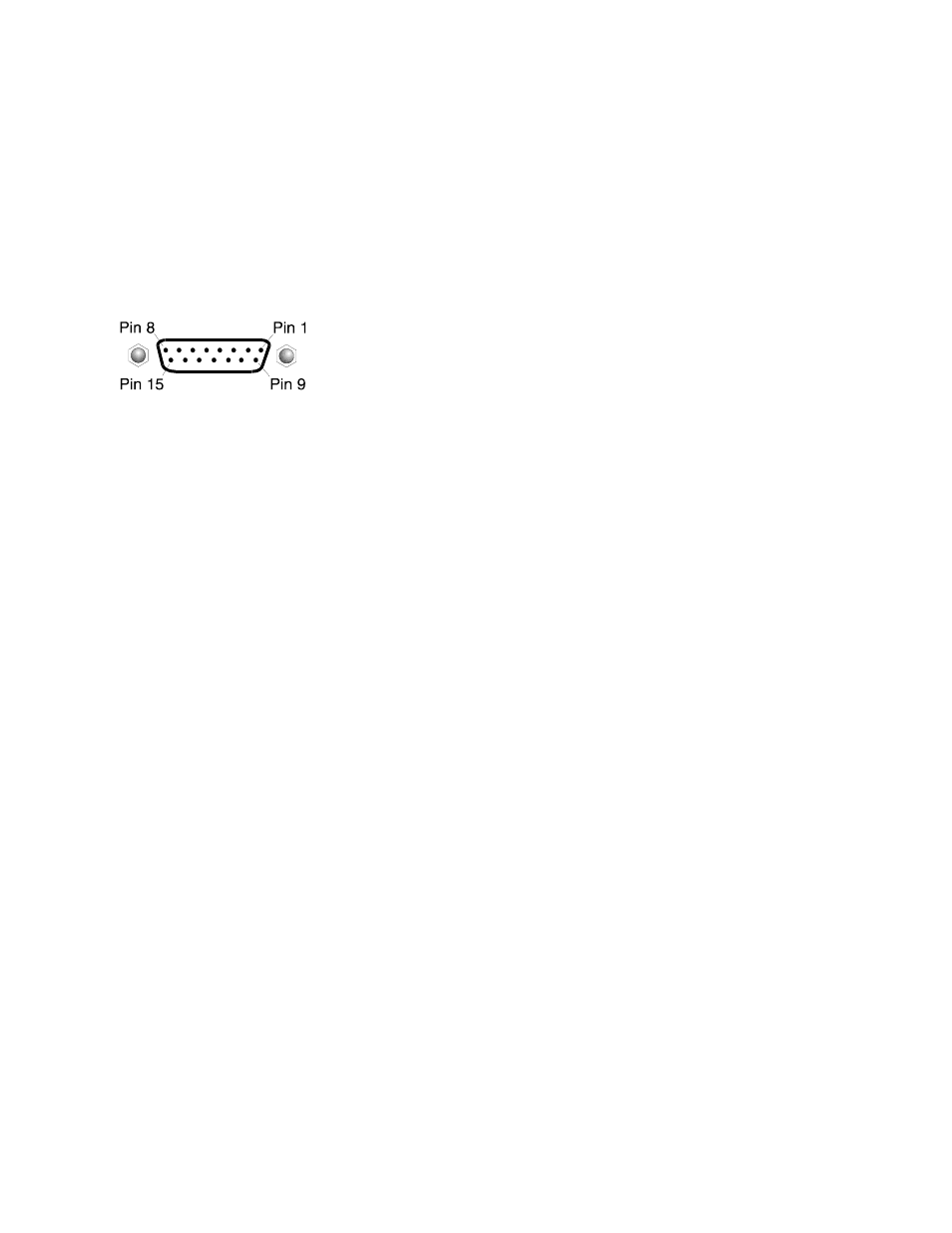
Control Port Pin Outs
The REMOTE CONTROL port is a Female 15 Pin D connector with the
following pin outs:
Pin 1
Select Channel 1
Pin 9
+5 volts DC
Pin 2
Select Channel 2
Pin 10 *Tally output for Channel 6
Pin 3
Select Channel 3
Pin 11 *Tally output for Channel 5
Pin 4
Select Channel 4
Pin 12 Tally output for Channel 4
Pin 5
*Select Channel 5
Pin 13 Tally output for Channel 3
Pin 6
*Select Channel 6
Pin 14 Tally output for Channel 2
Pin 7
Common
Pin 15 Tally output for Channel 1
Pin 8
Common
*Used only on 6-Input units
IN3546R STEREO AUDIO SWITCHER
The IN3546R Stereo Audio Switcher may be attached to the IN3500 Series via the REMOTE
CONTROL port. This provides a +5V power supply for the IN3546R Switcher and a control link.
When the IN3546R is attached to the control port using an IN9112 control link cable, the IN3546R will
automatically switch to the appropriate input channel, mirroring the input selected on the attached RGBS
switcher and adding audio-follow-video capability to the switcher.
INTERNAL FUSES
The IN3554/IN3556 switchers contain two internal fuses. If power is applied to the unit and the front
panel power LED will not light after the POWER switch has been activated, these fuses may be blown.
Open the case as described above and replace the blown fuses with new 200mA fuses.