Installation, Front and rear panel features and connections – Extron Electronics DVI 110 User Guide User Manual
Page 10
DVI 110 • Installation
44
Installation
This section describes the features of the DVI 110 front and rear panels and provides
instructions for cabling. It covers the following topics:
z
Front and Rear Panel Features and Connections
z
Front and Rear Panel Features and Connections
POWER
12V
0.4A MAX
DVI 110
DVI-D INPUT
DVI-D OUTPUT
2
3
1
4
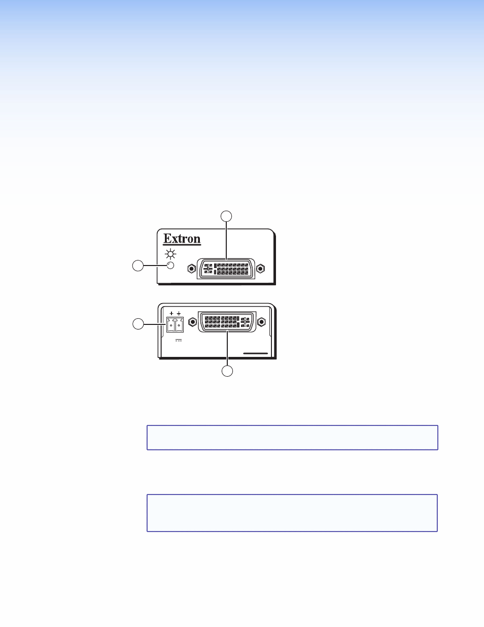
Figure 4.
DVI 110 Front and Rear Panels
a
Power and signal status LED — This dual-color LED lights amber when the
DVI 110 is receiving power. When a DVI input signal is present, the LED lights green.
NOTE: Use the provided external power supply to power the unit. The DVI 110
cannot receive power from the input device.
b
DVI-D output connector — Plug the cable from this single link format DVI-I
connector into a DVI output device. Output signals are digital only. (See the pin
assignment table on the next page.)
NOTES:
•
For the output, use cables that are 15 feet (4.5 m) or less.
•
Although this is actually a DVI-I connector, its analog pins are not
enabled. Only DVI-D signals are accepted.