Removing and installing a power supply module, Removing and installing a power supply module – Extron Electronics Fiber Matrix 6400 User Manual
Page 21
Refer also to the Fiber Matrix 6400 Switcher User’s Manual at
www.extron.com
.
Refer also to the Fiber Matrix 6400 Switcher User’s Manual at
www.extron.com
.
8
.
Gently slide the board or blank panel into the enclosure.
For an I/O board, slide the board toward the front panel
until it meets resistance.
9
.
Gently seat the board or panel in the backplane.
10
. Tighten the left and right knurled knobs/captive screws to
lock the board or panel in place.
N
If necessary, use a screwdriver to tighten the knurled
knobs/captive screws.
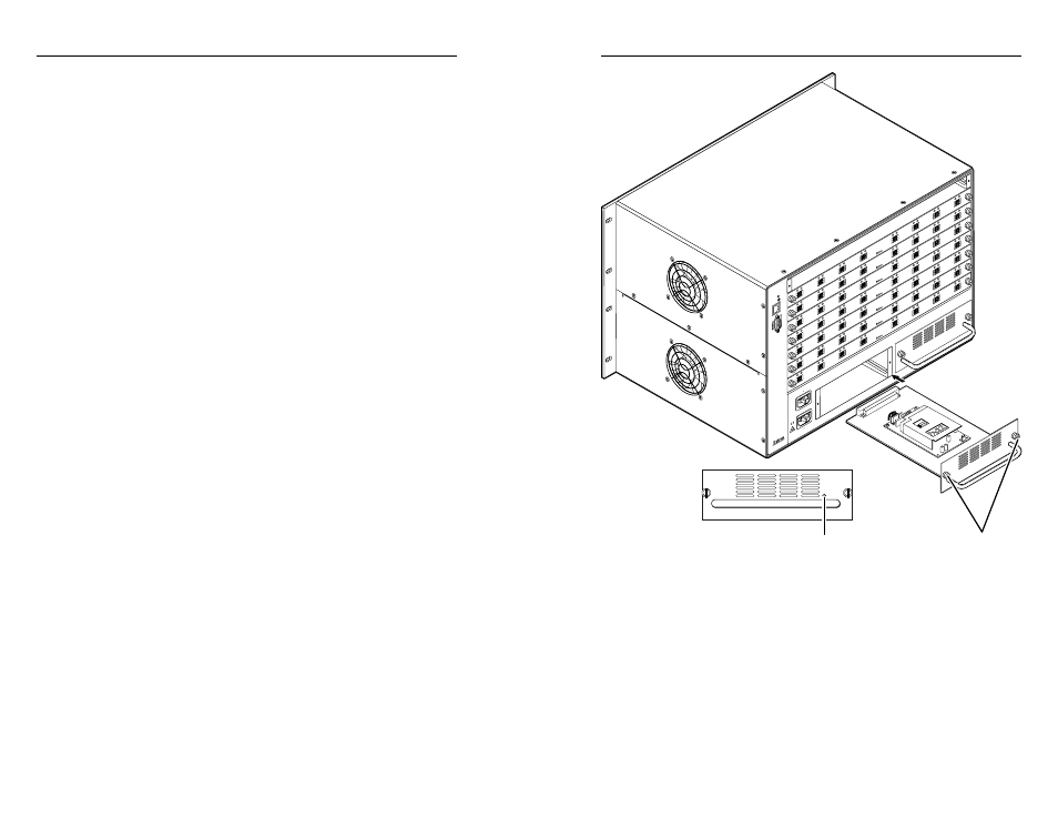
Removing and Installing a Power Supply
Module
The two power supply modules (primary power supply and
redundant power supply) are identical and hot-swappable.
Each power supply module has a 2-color LED, visible on
the rear panel, that indicates the status of the power supply
outputs. If the LED is lit green, the power supply is operating
normally. If the LED is lit red, the supply has failed and should
be replaced at the earliest opportunity.
N
The power supply modules are hot-swappable. Either
power supply can be removed without powering down the
switcher. You do not need to power down the switcher to
install a power supply.
1
.
Rotate the left and right knurled knobs to completely
loosen the captive screws.
2
.
Gently pull on the handle to loosen the power supply from
the backplane.
3
.
Slide the power supply out of the chassis.
4
.
Orient the power supply module to be installed with the
LED to the right.
5
.
Align the flanges on the power supply module with the
left and right power supply guides (see the next page).
6
.
Gently slide the power supply module into the enclosure
until the power supply meets resistance.
7
.
Gently seat the power supply in the backplane.
8
.
Tighten the left and right knurled knobs/captive screws to
lock the power supply in place.
N
If necessary, use a screwdriver to tighten the knurled
knobs/captive screws.
100-240V 50/60H
z
1.2A MAX.
100-240V 50/60H
z
1.2A MAX.
REDUND
ANT
PRIMAR
Y
1 - 8
9 - 16
17 - 24
25 - 32
33 - 40
41 - 48
49 - 56
57 - 64
LAN
ACT
LINK
RESET
ANAHEIM
, CA
PRIMAR
Y PO
WER SUPPL
Y
REDUND
ANT PO
WER SUPPL
Y
OU
T
IN
A
OU
T
IN
B
OUT
IN
C
OUT
IN
D
OUT
IN
E
OU
T
IN
F
OUT
IN
G
OUT
IN
H
OU
T
IN
A
OU
T
IN
B
OUT
IN
C
OUT
IN
D
OUT
IN
E
OU
T
IN
F
OUT
IN
G
OUT
IN
H
OU
T
IN
A
OU
T
IN
B
OUT
IN
C
OUT
IN
D
OUT
IN
E
OU
T
IN
F
OUT
IN
G
OUT
IN
H
OU
T
IN
A
OU
T
IN
B
OUT
IN
C
OUT
IN
D
OUT
IN
E
OU
T
IN
F
OUT
IN
G
OUT
IN
H
OU
T
IN
A
OU
T
IN
B
OUT
IN
C
OUT
IN
D
OUT
IN
E
OU
T
IN
F
OUT
IN
G
OUT
IN
H
OU
T
IN
A
OU
T
IN
B
OUT
IN
C
OUT
IN
D
OUT
IN
E
OU
T
IN
F
OUT
IN
G
OUT
IN
H
OU
T
IN
A
OU
T
IN
B
OUT
IN
C
OUT
IN
D
OUT
IN
E
OU
T
IN
F
OUT
IN
G
OUT
IN
H
Align with
plastic guides.
Knurled
Knobs
Power
LED
Fiber Matrix 6400 Switcher • Maintenance and Modifications
Maintenance and Modifications, cont’d
5-4
Fiber Matrix 6400 Switcher • Maintenance and Modifications
5-5