Front panel, Chapter 3 • front panel operation, Chapter three • front panel operation – Extron Electronics Fiber Matrix 6400 User Manual
Page 10: Chapter three, Front panel operation
Refer also to the Fiber Matrix 6400 Switcher User’s Manual at
www.extron.com
.
Front Panel
FIBER MATRIX 6400
CONTROL
CONFIG
ENTER
PRESET
VIEW
ESC
FIBER OPTIC DIGITAL MATRIX SWITCHER
POWER SUPPLY
PRIMARY
REDUNDANT
7
8
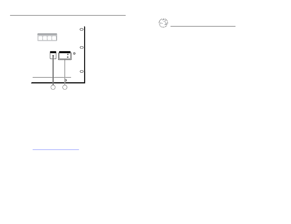
Figure 2-7 — Front panel configuration port
g
Configuration port —
If desired, connect a control system
or computer to the front panel Configuration (RS-232) port.
Use an optional 9-pin D to 2.5 mm mini jack TRS RS-232
cable, part #70-335-01.
h
Primary and Redundant Power Supply LEDs —
Green —
Indicates that the associated power supply is
operating within normal tolerances.
Red —
Indicates that the associated power supply is operating
outside the normal tolerances or has failed. See chapter 4,
“Maintenance and Modifications”, to replace the power supply.
3
Chapter Three
Front Panel Operation
Creating.a.Tie
Viewing.Ties.(and.Muting.Outputs)
Saving.or.Recalling.a.Preset
Locking.Out.the.Front.Panel.(Executive.Mode)
Fiber Matrix 6400 Switcher • Installation
Installation, cont’d
2-6
Fiber Matrix 6400 Switcher