Foxbox dvi plus • setup guide (cont’d), Control and indications, Step 4 — remote connector – Extron Electronics FOXBOX DVI Plus User Manual
Page 2: Step 5 — power, Operation, Mode switch, Indications
Step 4 — Remote Connector
Connect a host device to either unit’s front panel Configuration connector via the 9-pin D to 2.5 mm mini jack TRS RS-232
cable that is included with the TX model or available separately using part #70-335-01. Refer to the FOXBOX DVI Plus
User Guide for detailed information about the using the Simple Instruction Set (SIS
™
) commands and the Windows
®
-based
FOX Extender program to set up and operate the transmitter and receiver and to take advantage of the various adjustments
and test patterns available on the FOXBOX units.
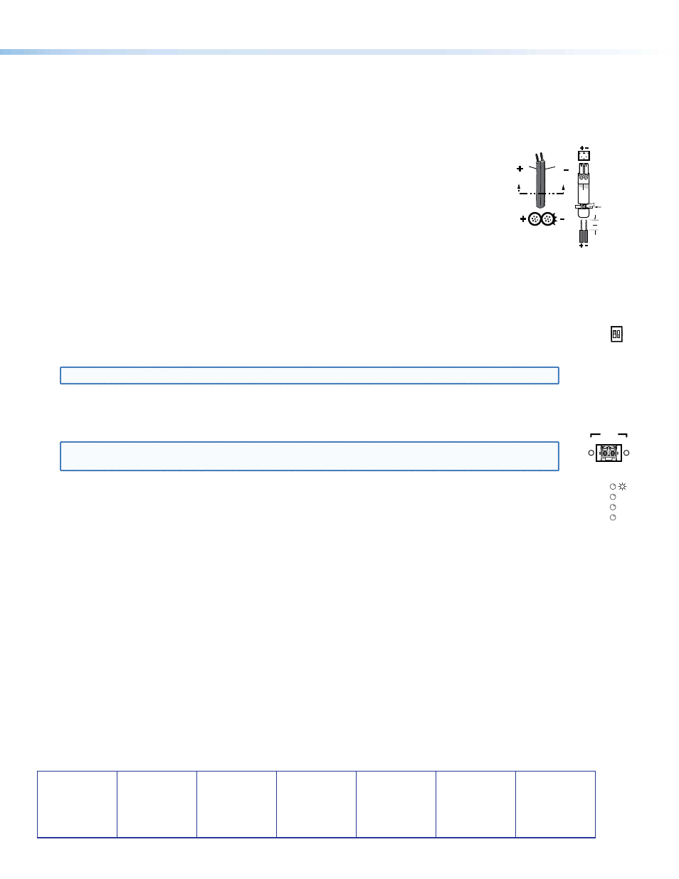
Step 5 — Power
Connect using an external power supply as shown on the right.
Control and Indications
Operation
After all receivers, the transmitter, and their connected devices are powered up,
the system is fully operational. If any problems are encountered, verify that the
cables are routed and connected properly and that all display devices have identical resolutions and refresh rates. If your
problems persist, call the Extron S
3
Sales & Technical Support Hotline.
Mode Switch
Mode switch (receiver) — To connect the received optical input to another receiver in a daisy chain configuration,
MODE
1 2
set DIP switch 1 to up as shown.
DIP switch 2 is not used.
NOTE: Up to 10 properly-configured receivers can be connected in a daisy chain to a single transmitter.
Indications
Tx Link and Rx Link LEDs — When lit, the link is active (light is output [Tx] or received [Rx]).
OPTICAL
Tx Rx
LINK
LINK
NOTE: The Link LEDs indicate light transmission only, not whether there is data encoded in the optical
link.
Power LED — This LED lights to indicate that power is applied to the unit.
DVI
OVER
TEMP
AUDIO
Over Temp(erature) LED — This LED lights to indicate that the unit is operating at a dangerously high
temperature (approximately 167° F [75° C]) and that equipment damage is imminent.
DVI LED — This LED lights on both units when the transmitter detects a signal on its video input. This LED lights on
the receiver when the transmitter detects a DVI video signal.
Audio LED — This LED lights on both units when the transmitter detects a low level audio signal for a short period of time.
It goes dark if the audio signal drops below the minimum threshold for a short period of time.
Power Supply
Output Cord
SECTION A–A
Ridges
Smooth
A
A
Captive
Screw
Connector
Tie Wrap
3"
16 (5 mm) Max.
Extron USA - West
Headquarters
+800.633.9876
Inside USA/Canada Only
+1.714.491.1500
+1.714.491.1517 FAX
Extron USA - East
+800.633.9876
Inside USA/Canada Only
+1.919.863.1794
+1.919.863.1797 FAX
Extron Europe
+800.3987.6673
Inside Europe Only
+31.33.453.4040
+31.33.453.4050 FAX
Extron Asia
+800.7339.8766
Inside Asia Only
+65.6383.4400
+65.6383.4664 FAX
Extron Japan
+81.3.3511.7655
+81.3.3511.7656 FAX
Extron China
+400.883.1568
Inside China Only
+86.21.3760.1568
+86.21.3760.1566 FAX
Extron Middle East
+971.4.2991800
+971.4.2991880 FAX
© 2011 Extron Electronics. All rights reserved.
www.extron.com
68-1464-51
Rev B
05 11
2
FOXBOX DVI Plus • Setup Guide (Cont’d)