Extron Electronics FOXBOX DVI Plus User Manual
Foxbox dvi plus • setup guide, Installation, Step 1 — mounting
This card provides quick start instructions for an experienced installer to set up and
operate an Extron
®
FOXBOX DVI Plus transmitter and receiver.
NOTES:
• Only the FOXBOX Rx DVI Plus receiver can accept input from a
FOXBOX Tx DVI Plus transmitter.
•
The FOXBOX Rx DVI Plus receiver can accept inputs from any FOX
500 or FOXBOX transmitter, including VGA models.
Installation
Step 1 — Mounting
Turn off or disconnect all equipment power sources and mount the transmitter and receiver as required.
Step 2 — Input and Output Connections
a.
Connect a DVI video source to the to the Input connector on the transmitter and the a DVI Display to the
DVI-D INPUT
Ouput connectors on the receiver.
b.
Connect unbalanced stereo or mono audio input and an audio output device to the 3.5 mm mini jack audio
AUDIO
ports on both units.
c.
If you want the FOXBOX units to pass serial data or control signals, such as for serial control of a projector,
ALARM
Tx Rx
1 2
RS-232
OVER FIBER
connect the master device to the transmitter and the slave device using the first three poles of the RS-232
Over Fiber/Alarm 5-pole captive screw connectors on both units.
NOTE: For RS-232 responses (from the receiver to the transmitter), you must install the cable in step 3b and leave
the receiver in normal configuration.
d.
For remote monitoring of the status of the optical links, connect a locally constructed or obtained device to
RS-232
OVER FIBER
ALARM
Tx Rx
1 2
the two Alarm poles of the units’ RS-232 Over Fiber/Alarm 5-pole captive screw connectors. The two poles
are shorted together when no light is detected.
NOTES: The Alarm port on the transmitter reports the status of the Rx light link.
The Alarm port on the receiver reports the status of the Tx light link.
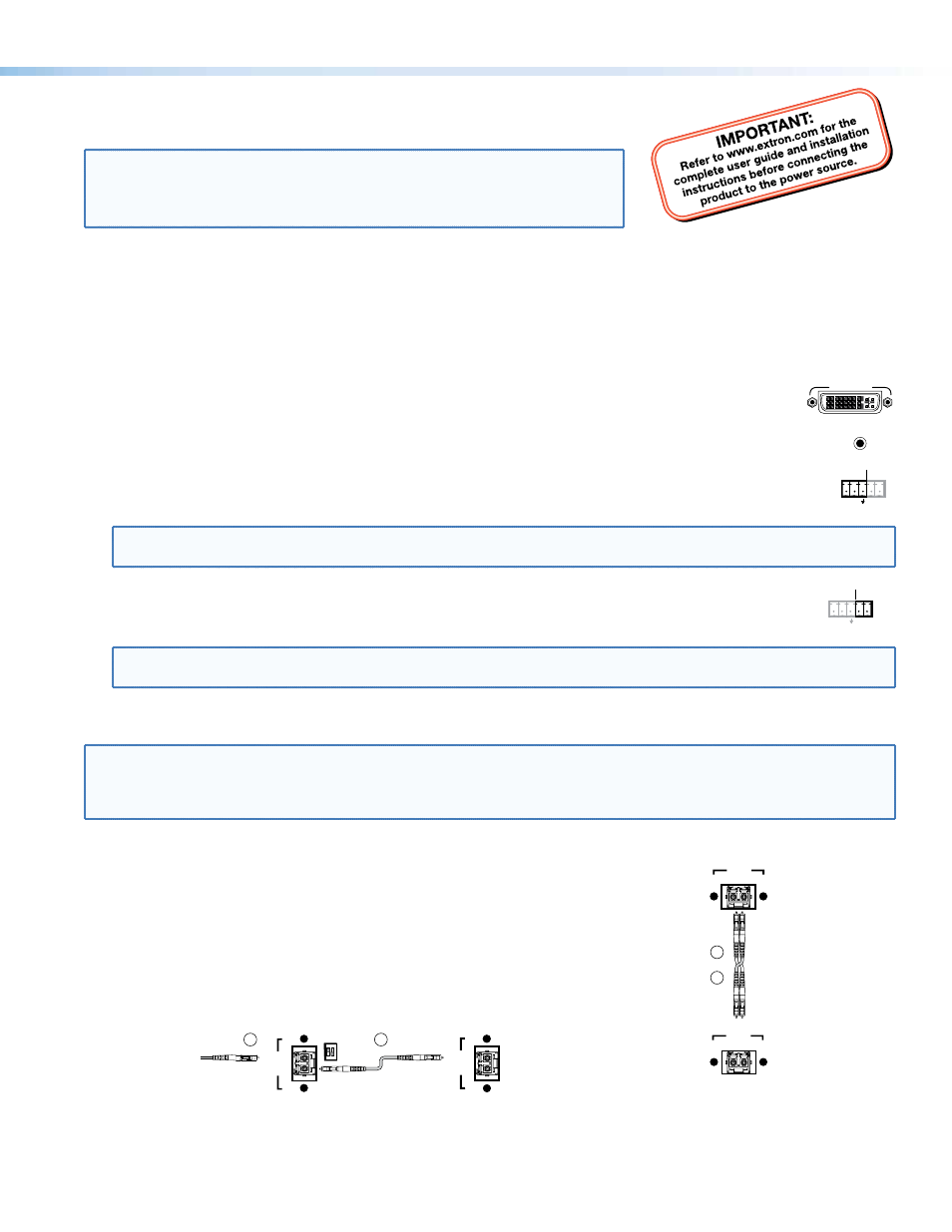
Step 3 — Throughput Connections
NOTE: You can connect the transmitter and one or more receivers in one of three ways:
• One way (transmitter to receiver) only, perform step 3a.
• Two way (transmitter to receiver and return), perform steps 3a and 3b.
• One way (transmitter to receiver) with daisy chain (receiver to receiver), perform steps 3a and 3c.
a.
Connect a fiber cable between the Tx port on the transmitter and the Rx port on
the receiver.
OPTICAL
Tx Rx
LINK
LINK
OPTICAL
Tx Rx
LINK
LINK
and
Transmitter
Receiver
3a
3b
b.
If you want the receiver to send return serial data (such as responses from a
controlled device) to the transmitter, connect a fiber cable between the Tx port
on the receiver and the Rx port on the transmitter.
c.
If you want a receiver to daisy chain the optical signal to another receiver (up to
10 receivers in a daisy chain):
z
Connect the Tx port on the receiver to the Rx port on another receiver.
z
Set the Mode DIP switch 1 up on first receiver.
OPTICAL
Tx
Rx
LINK
LINK
From Transmitter or
Daisy Chaining Receiver
MODE
1 2
Receiver
Receiver
3a
3c
OPTICAL
LINK
LINK
Tx
Rx
1
FOXBOX DVI Plus • Setup Guide