Dvs 510 series • setup guide (continued), Locking the front panel (executive mode) – Extron Electronics DVS 510 Series Setup Guide User Manual
Page 2
DVS 510 Series • Setup Guide (Continued)
2
z
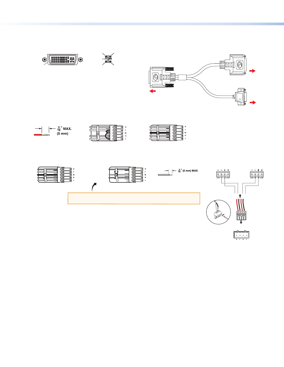
Video inputs 7/8 and 9/10 — Connect two DVI video sources, two RGB/YUV sources, or one DVI and one RGB
source to these DVI-I connectors. The analog portions of these connectors are identified as inputs 7 and 9, while the
DVI portions are inputs 8 and 10. These connectors feature EDID emulation.
1
8
17
24
9
C1
C4
C2
C3
C5
DVI-I Input Connector
Digital (Inputs 8 and 10)
Analog (Inputs 7 and 9)
Breakaway cable: You can use an optional Extron
DVIIM-VGAF/DVIIF “Y” DVI adapter cable (shown at
right) to connect one analog RGB or YUV source and
one DVI source to one or both of these connectors.
This cable enables both an analog and a DVI source
device to be connected to these ports and active at
the same time.
4.
Connect audio input devices to the Audio Input captive screw connectors (
h
on the rear panel diagram on the
previous page), as shown below.
5.
Connect video output devices to the Video Output connectors (
f
and
g
in the diagram).
6.
Connect audio output devices to the 5-pole Variable (
j
) and Fixed (
k
) Audio Output captive screw connectors.
DVS 510 SA: Connect speakers to the internal amplifier through the 4-pole
Amplified connector (
i
) (see also the illustration at right).
z
Connect the red speaker wire to the positive (+) pin on the Amplified connector.
z
Connect the black speaker wire to the negative (–) pin on the connector.
7.
Connect control devices:
z
LAN Ethernet port — Connect the DVS 510 to an Ethernet LAN or WAN via this RJ-45 connector (
n
) to control
the scaler from a remote location using an Internet browser on a computer.
z
RS232 port — For serial RS-232 or RS-422 control, connect a host computer or control system to the DVS via this
9-pin D-sub connector (
o
).
z
The front panel has an additional serial port (RS-232 only) (see “Front Panel Features” on the next page).
The default protocol for both ports is 9600 baud, 1 stop bit, no parity, 8 data bits, and no flow control.
8.
Connect power to the DVS 510 by plugging a standard IEC power cord (provided) from a 100 to 240 VAC, 50-60 Hz
power source into the power receptacle (
a
).
Locking the Front Panel (Executive Mode)
To prevent accidental changes to settings, you can lock the DVS 510 front panel controls by placing the scaler in lock
(executive) mode 1 or 2. While the DVS is in lock mode, RS-232 or RS-422 and IR remote control remain available.
z
Lock mode 1 locks all front panel functions. This mode can be enabled or disabled only by SIS commands.
z
Lock mode 2 locks all front panel functions except input selection, PIP, volume control, and Auto-Image™. To enable
lock mode 2, press and hold the Position and Size buttons simultaneously until Executive Mode 2 Enabled appears in
the LCD window (approximately 2 seconds).
To exit lock mode 2, press and hold the Position and Size buttons again until Executive Mode Disabled appears in
the LCD window (approximately 2 seconds).
Extr
on
DVI-I Male Connector
Female 15-pin HD Connector
FOR ANALOG ONLY
Female DVI-I Connector
FOR DIGITAL ONLY
To DVS 510 Female DVI-I
Input Connector (Inputs 7 – 10)
To a DVI
Input Source
To an RGB or
YUV Analog
Input Source
DVS 510 SA
Rear Panel
Speaker 1
Speaker 2
L
R
4/8
Ohms
4-pole Captive
Screw Connector
Audio Output
to Speakers
AMPLIFIED
Balanced Audio Output
Unbalanced Audio Output
Tip
Ring
Tip
Ring
LR
Sleeve
Do not tin the wires!
Tip
NO Ground Here
Sleeve
NO Ground Here
Tip
LR
CAUTION:
For unbalanced audio, connect the sleeves to ground.
DO NOT
connect the sleeves to negative (–) contacts.
Unbalanced Stereo Input
Balanced Stereo Input
LR
LR
Ring
Sleeve (s)
Tip
Sleeve
Tip
Sleeve
Tip
Tip
Ring
Do not tin the wires!