Installation and operation, cont’d, Rear panel connections and controls – Extron Electronics DVI-RGB 150 User Manual
Page 9
DVI-RGB 150 • Installation and Operation
Installation and Operation, cont’d
2-6
DVI-RGB 150 • Installation and Operation
2-7
7
.
Slide the device in or out until it is in the desired position.
Tighten the screws installed in step 2.
If the screws are inaccessible to a screwdriver:
a
. Mark the location of the brackets relative to the screws.
b
. Remove the transmitter or receiver from inside the
furniture.
c
. Tighten the screws.
d
. Replace the unit inside the surface (step 6).
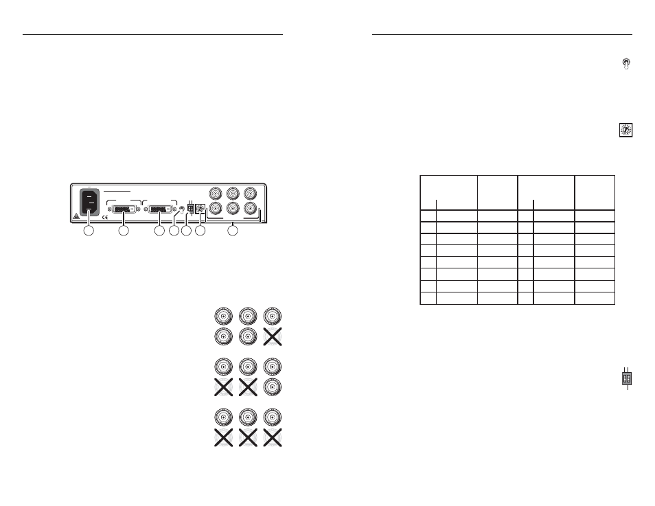
Rear Panel Connections and Controls
a
Input connector — Connect a single link of direct digital video
to this 25-pin DVI-D connector (fi gure 2-5) using the included
cable.
100-240 50/60 Hz
0.35A MAX
OUTPUT
INPUT
BUFFERED
LOOP-THROUGH
R
H
G
V
B
S
SOG ON/OFF
REFRESH
DDC
SOURCE
MONITOR
HIGH
LOW
SELECTOR
OUTPUT
RESOL.
DVI-RGB 150
2
1
5
7
3
6
4
Figure 2-5 — DVI-RGB 150 rear panel
b
Buffered Loop-through connector — If desired, connect a direct
digital local monitor to this 25-pin DVI-D connector.
c
Output connectors — Connect an RGB display to these female
BNC connectors.
For RGBHV video —
Connect to fi ve
BNC connectors as shown at right.
Ensure that the SOG On/Off switch
(
f
)
is turned off.
For RGBS video —
Connect to four BNC
connectors as shown at right. Ensure that
the SOG On/Off switch
(
f
) is turned off.
For RGsB video —
Connect to three BNC
connectors as shown at right. Ensure that
the SOG On/Off switch
(
f
) is turned on.
R
H
G
V
B
S
R
H
G
V
B
S
R
H
G
V
B
S
DDC
SOURCE
MONITOR
SELECTOR
d
DDC Source switch — Set this switch to the Monitor (up)
position to connect the DDC channel between the direct
digital video source and the local monitor.
Set this switch to the Selector (down) position to connect
the DDC channel between the direct digital video source
and the built-in DVI-RGB 150 DDC logic.
e
Output Resolution rotary switch —
If the DDC Source
switch
(
d
) is in the Selector position, set this switch to the
appropriate position to select the desired video resolution.
Use the Refresh DIP switch
(
f
) to select the refresh
rate. The table below identifi es the switch positions and the
associated resolutions and vertical refresh rates.
Pos. Resolution
Output Resol.
Switch
Refresh
DIP Switch
0
640x480
1
2
852x480
3
1024x768
6
8
9
A
B
60 Hz 75
60 Hz 75
60 Hz 75
60 Hz 75
4
5
1024x852
1280x768
60 Hz 75
60 Hz 75
7
800x600
1280x1024
1366x768
1400x1050
1600x1200
480p
Pos. Resolution
60 Hz 75
60 Hz 75
60 Hz 60
60 Hz 60
60 Hz 60
<
>
Dwn
Up
1365x768
60 Hz 75
C
D
E
F
576p
1080i
1080p
720p
50 Hz 50
50 Hz 60
50 Hz 60
50 Hz 60
Refresh
DIP Switch
<
>
Dwn
Up
Output Resol.
Switch
N
Many monitors will not support all of the resolutions and
refresh rates shown. If you get no display, try a different
rate.
f
SOG (Sync on Green) On/Off switch— Set this switch to
the On (up) position to enable SOG for RGsB video. Set
this switch to the Off (down) position to disable SOG for
RGBS or RGBHV video.
Refresh switch —
If the DDC Source switch
(
d
) is in the
Selector position, set this switch either up or down to select
the refresh rate of the selected output. See the table above.
g
AC power connector — Plug a standard IEC power cord
into this connector to connect the interface to a 100 to 240VAC,
50 Hz or 60 Hz power source.
SOG ON/OFF
REFRESH
HIGH
LOW
OUTPUT
RESOL.