Extron Electronics DTP DVI 330 User Guide User Manual
Page 10
DTP DVI 330 Tx/Rx Transmitter and Receiver • Installation and Operation
4
b
Local Output connector — If desired, connect a DVI monitor for local monitoring of
the input digital image.
NOTES:
•
The local output is limited to a data rate of 4.95 Gbps (1.65 Gbps per color).
•
In a system where the local output is not used, ensure that you power up the
end display first before the video source. Route the DDC to the remote end
(see the DDC Route DIP switch [see
on page 9]).
c
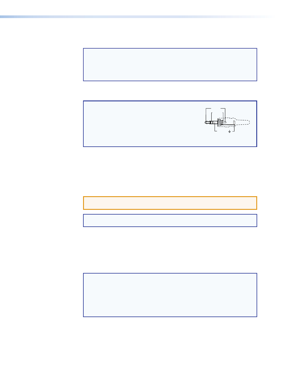
Audio input connector — If desired, plug an analog audio input into the transmitter
via this stereo mini jack connector.
NOTE: The analog audio input on this connector is in
addition to the digital audio that may be embedded
in the DVI input. See the figure at right to identify
the connector tip, ring, and sleeve when you
are making connections for the transmitter from
existing audio cables. A mono audio connector
consists of the tip and sleeve. A stereo audio
connector consists of the tip, ring, and sleeve.
Sleeve ( )
Ring (-)
Tip (+)
3.5 mm Stereo Plug Connector
(balanced)
d
RS-232 and IR connector — Connect a serial RS‑232 signal, a modulated IR
signal, or both to this 3.5 mm, 5‑pole captive screw connector for bidirectional RS‑232
and IR communication (see
RS-232 and IR connector wiring
to wire the
connector).
e
DTP Output RJ-45 connector — Connect one end of a TP cable to this RJ‑45
female connector on the transmitter. Ensure the opposite end of this cable is connected
to the receiver DTP Input RJ‑45 connector (see
ATTENTION: Do not connect this device to a telecommunications or computer
data network.
NOTE: See
TP cable termination and recommendations
on page 6 to properly
wire the RJ‑45 connectors and for detailed
NOTES.
Signal LED — Indicates the unit is receiving a TMDS clock signal on the DVI input.
Link LED — Indicates a valid link is established between the units on the DTP input
and output cable.
f
Power input connector — Plug the included external 12 VDC power supply into
either this 2‑pole connector
or the power input connector on the receiver (
to wire the connector.
NOTES:
•
One power supply is included with the transmitter and
normally can power
both units.
•
If you have removed the ground jumpers (see
on page 11) because of ground potential differences, one DTP DVI 330 unit
cannot remotely power the other unit. Each unit requires a local power
supply.