Operation, Rs-232 and ir connector wiring – Extron Electronics DTP HDMI 230 User Guide User Manual
Page 15
DTP HDMI 230 Tx/Rx Transmitter and Receiver • Installation and Operation
9
RS-232 and IR connector wiring
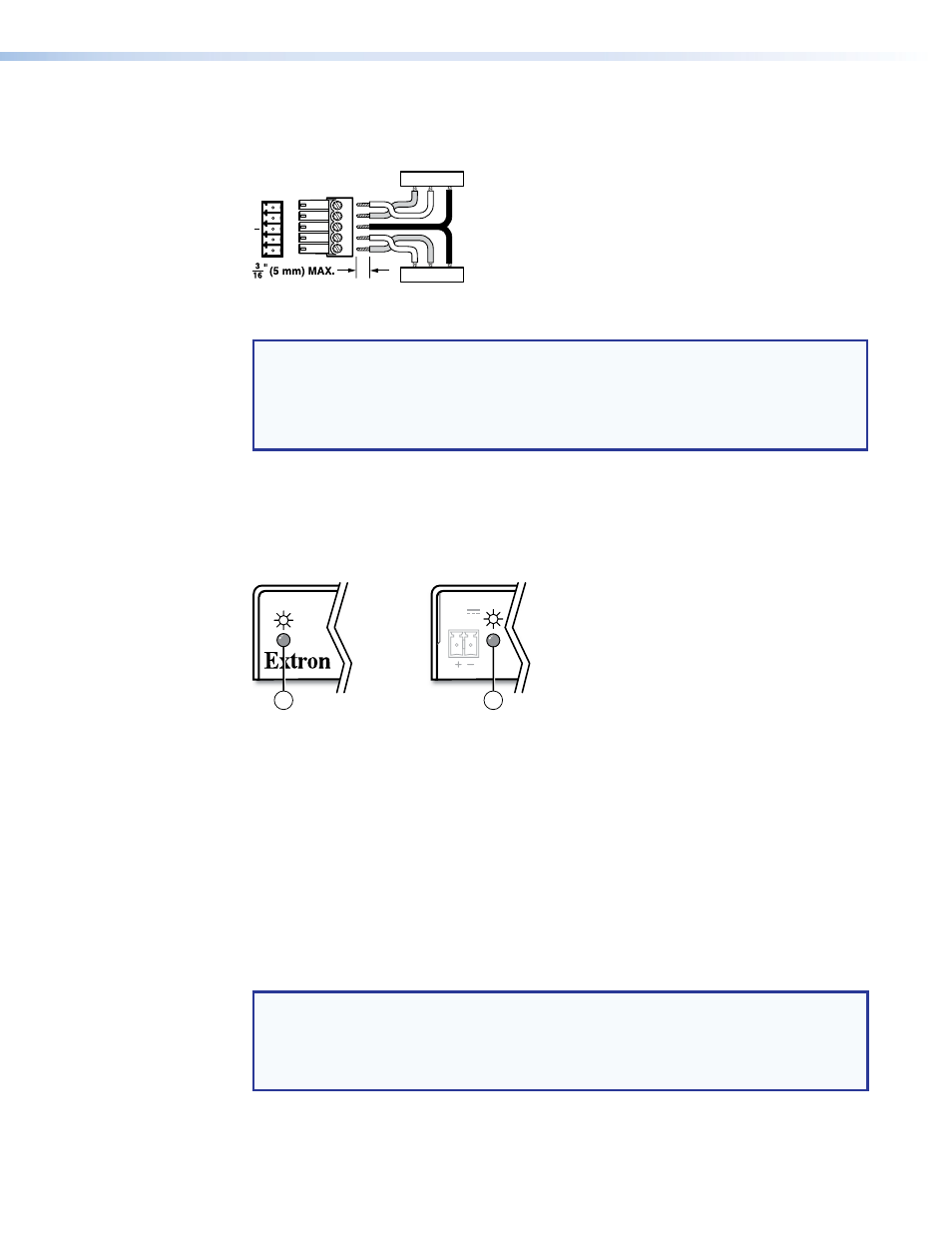
Figure 7 shows how to wire the RS‑232 connector.
Tx/Rx
Pins
Rx
G
Tx
RS-232
IR
Rx
Tx
Tx
Rx
Rx
Tx
Gnd
Gnd
IR Device
RS-232 Device
Figure 7.
RS-232 Connector Wiring
NOTES:
•
The IR Tx and Rx line pair and the RS‑232 Tx and Rx line pair must each cross
once between this connector and the source or destination.
•
The length and preparation of exposed wires is important (see the second and
third audio connector
Operation
Figure 8 shows the location of the power indicators on the front and rear panels of the
transmitter and receiver.
Rear Panel
Rear Panel
Front Panel
Front Panel
POWER
12V
0.6 A MAX
2
1
Figure 8.
Power Indicators
a
Power (and signal) LED (front panel) —
Amber — The unit is receiving power, either locally or remotely (on the DTP cable).
Green — The unit is receiving an active HDMI input, either on the HDMI input if a
transmitter, or transmitted on the DTP cable if a receiver.
b
Power LED (rear panel) —
Amber — The unit is receiving power remotely (on the DTP cable).
Green — The unit is receiving power locally.
After the transmitter, the receiver, and their connected devices are powered up, the system is
fully operational. If any problems are encountered, ensure all cables are routed and
connected properly.
NOTE: Ensure that the video source and display selected for the DDC are properly
connected to the transmitter and receiver pair, and that the transmitter, the receiver,
and the display have power applied
before power is applied to the video source.
If the other devices are not turned on before the video source, the image may not
appear.