Receiver connections, 45 connector (see, Item – Extron Electronics DTP HDMI 230 User Guide User Manual
Page 11
DTP HDMI 230 Tx/Rx Transmitter and Receiver • Installation and Operation
5
e
Power input connector — Plug the included external 12 VDC power supply into
either this 2‑pole connector
or the power input connector on the receiver (
j
on
to wire the connector.
NOTES:
•
One power supply is included with the transmitter and
normally can power
both units.
•
If you have removed the ground jumpers (see
on page 11) because of ground potential differences, one DTP HDMI 230
unit
cannot remotely power the other unit. Each unit requires a local power
supply.
Receiver Connections
DTP HDMI 230 Rx Rear Panel
Front Panel
DTP HDMI 230 Rx
RS-232
IR
Tx Rx
Tx Rx
G
L
R
POWER
12V
0.7A MAX
AUDIO
SIG LINK
DTP IN
OUTPUTS
OVER DTP
9
8
10
6
7
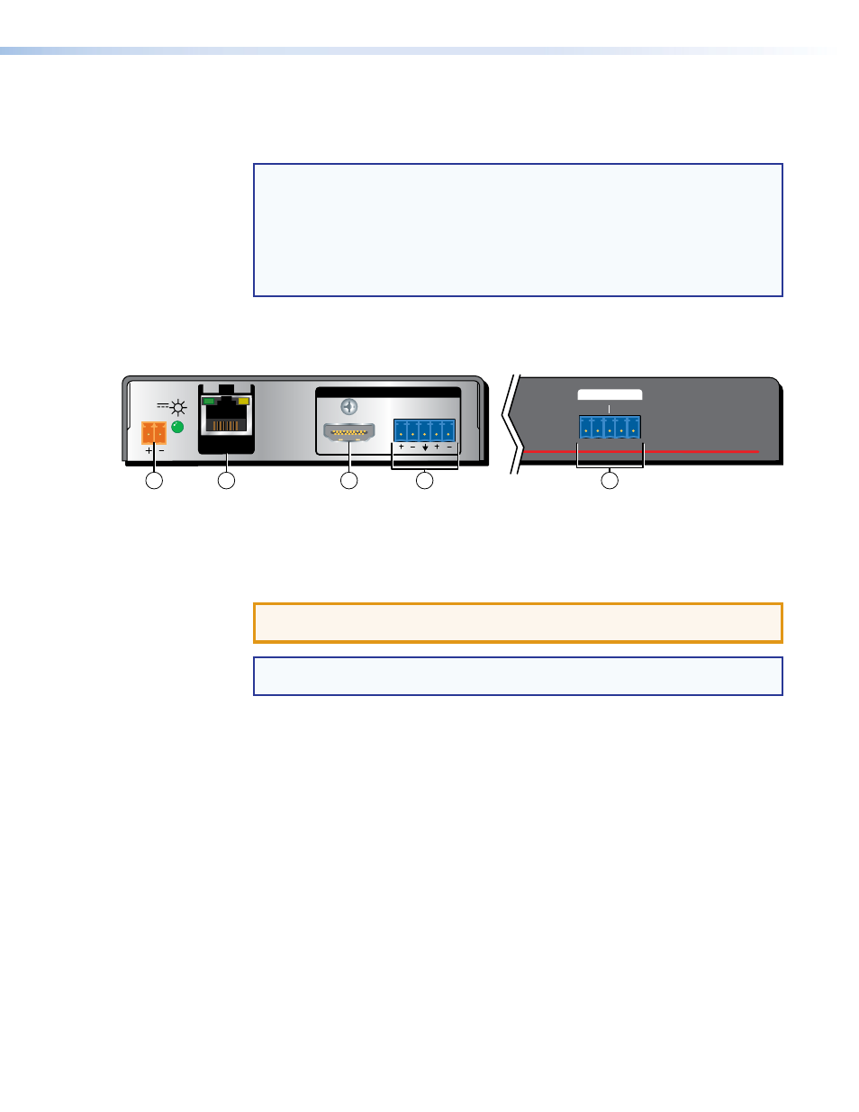
Figure 3.
DTP HDMI 230 Rx Connectors
f
DTP Input RJ-45 connector — Connect one end of the TP cable from the transmitter
output connector to this RJ‑45 female connector. Ensure the opposite end of this
cable is connected to the transmitter DTP Output RJ‑45 connector (see
previous page).
ATTENTION: Do not connect this device to a telecommunications or computer
data network.
TP cable termination and recommendations
on page 7 to properly
wire the RJ‑45 connectors and for detailed
NOTES.
Signal LED — Indicates the unit is receiving a valid signal on the DTP In connector.
Link LED — Indicates a valid link is established between the units on the DTP input
and output cable.
g
HDMI output connector — Connect a display with an HDMI input port (or DVI input
port, with an appropriate adapter) to display the transmitted direct digital image.