Specifications, Introduction – John Wood Takagi - 910 User Manual
Page 3
3
SPECIFICATIONS
Model
910
Natural Gas Input
(Operating Range)
Min: 15,000 BTU/h
Max: 380,000 BTU/h
Propane Input
(Operating Range)
Min: 15,000 BTU/h
Max: 380,000 BTU/h
Gas Connection
1” NPT
Water Connections
1” NPT
Water Pressure
15 - 150 psi*
Natural Gas Inlet
Pressure
Min.: 5” WC
Max.: 10.5” WC
Propane Inlet Pressure
Min.: 8” WC
Max:. 14” WC
Manifold Pressure
Natural: 2.8” WC
Propane: 3.8” WC
Weight
50.8Kg (112 lbs.)
Dimensions
H 643mm (25.3 in.) ×
W 630mm (24.8 in.) ×
D 300mm (11.8 in.)
Ignition
Electric Ignition
Electric
Supply
120 VAC / 60 Hz
Consumption
Operation
178 W (1.48A)
Standby
16 W (0.13A)
Freeze-
Protection
271 W (2.26A)
*40 psi or above is recommended for maximum flow
NOTE
* All references to the 910 also refer to the 910 ASME
model
* Check the rating plate to ensure this product matches
your specifications.
* The manufacturer reserves the right to discontinue,
or change at any time, specifications or designs
without notice and without incurring obligations.
INTRODUCTION
This manual provides information necessary for the
installation, operation, and maintenance of the 910 water
heater.
The model description is listed on the rating plate which
is attached to the front cover of the water heater.
Please read all installation instructions completely before
installing this product.
If you have any problems or questions regarding this
equipment, consult with the manufacturer or its local
representative.
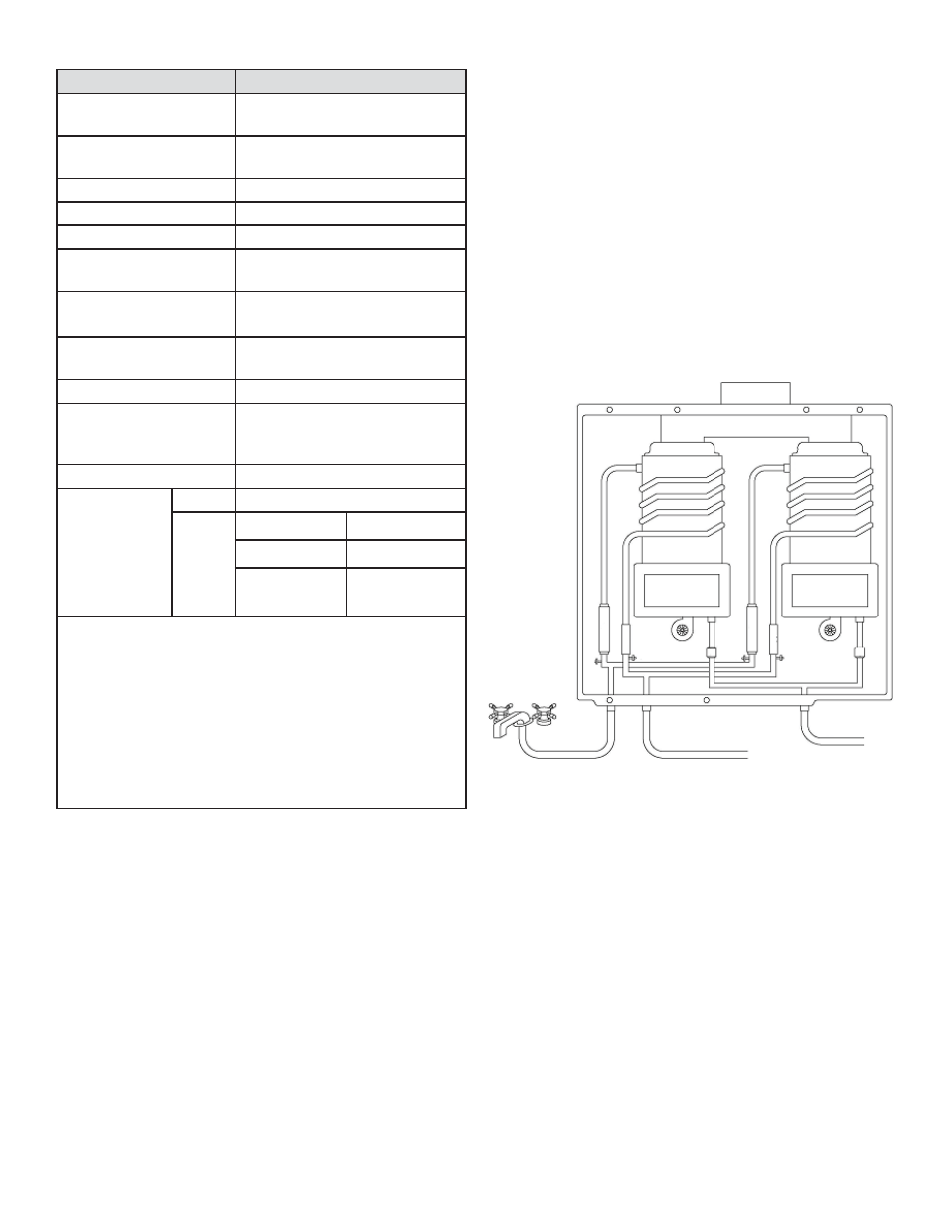
The 910 is an on-demand, tankless water heater designed
to efficiently supply endless hot water for your needs.
The 910 has two heat exchangers. The primary and sec-
ondary heat exchangers alternate roles, extending the
life of the 910 (see pg. 4).
The principle behind the 910 Water Heater is simple:
Burner
Cold Water
Inlet
Fan
Hot Water
Outlet
1. Water control
valve
2. Flow sensor
3. Gas Valve
4. Temperature
sensor
Gas
Inlet
Heat
exchanger
Heat
exchanger
Burner
Fan
Exhaust
4
3
3
2
1
2
1
4
4
4
* This diagram illustrates tankless water heater design con-
cepts only and is not accurate to the 910 physical descrip-
tion.
A hot water tap is turned on.
Water enters the heater.
The water flow sensor detects the water flow.
The computer automatically ignites the burner.
Water circulates through the heat exchanger and then
gets hot.
The computer will modulate the gas supply valve and
water flow to produce the right amount of hot water at the
correct temperature.
When the tap is turned off, the unit shuts down.
•
•
•
•
•
•
•
1.
2.
3.
4.
5.
6.
7.