Warning, Anode removal and replacement, Thermostat removal and replacement – John Wood SpaceSaver (2.5 Gallon) User Manual
Page 13: High limit switch removal and replacement, Service
13
Anode Removal and
Replacement
1. Using a 7mm wrench, remove the nut securing the
anode.
2. Unscrew and remove anode.
3. Screw in the new anode and secure with the retaining
nut.
4. Follow instructions for replacing the element in “Heating
Element Cleaning/Replacement.”
Thermostat Removal and
Replacement
Removal
1. Disconnect the electrical power.
2. Remove the front panel, see the “Removing the Front
Panel” section in this manual. Remove the insulation
pad.
3. Using a 7mm wrench, remove the two nuts securing
the temperature sensor.
4. Remove the 3 wires (white, brown, and green/yellow)
from the thermostat at the spade connections, carefully
taking note of the original location of each wire.
5. Unscrew the 2 screws securing the thermostat to the
front panel and remove thermostat.
Replacement
1. Place the new thermostat against the front panel and
secure it with the two screws.
2. Reattach the wires at the spade connections, taking
care to place them in their original locations. Be sure
to push the connector completely onto the spade
terminals.
3. Secure the temperature sensor to the tank by
tightening the nuts. Be sure the sensor is firmly in
contact with the tank surface.
4. Replace the insulation block and the front panel.
5. Reconnect the electrical power.
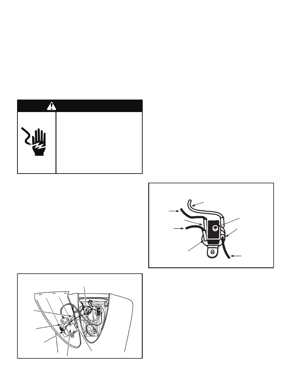
High Limit Switch Removal
and Replacement
1. Disconnect the electrical power.
2. Remove the front panel, see the “Removing the Front
Panel” section in this manual. Remove the insulation
pad.
3. Remove the four wires connected to the switch, taking
care to note the original placement of each wire.
4. Using a 7mm wrench, loosen and remove the nuts
securing the high limit switch to the tank.
5. Remove the old switch and position the new switch in
place on the tank.
6. Replace and tighten the nuts so the high limit switch is
firmly in contact with the tank surface.
7. Replace the four wires, taking care that they are
replaced into their original positions.
8. Replace the insulation block and the front panel.
9. Reconnect the electrical power.
Service
If a condition persists or you are uncertain about the
operation of the water heater contact a service agency.
Use this guide to check a “Leaking” water heater. Many
suspected “Leakers” are not leaking tanks. Often the
source of the water can be found and corrected.
If you are not thoroughly familiar with your water heater and
safety practices, contact a qualified installer to check the
water heater.
Figure 13
Thermostat
Wiring
YELLOW/
GREEN
WIRE
TEMPERATURE SENSOR
WHITE
WIRE
BROWN
WIRE
GREEN WIRE
THERMOSTAT
Failure to do so can result in
death or electrical shock.
Replace all parts and panels
before operating.
Disconnect power before
servicing.
Electric Shock Hazard
WARNING
Figure 14
High Limit Switch
Wiring
BLACK
WIRE
WHITE
WIRE
BROWN
WIRE
BLUE
WIRE
TERMINAL
1
RED RESET
BUTTON
TERMINAL
3
TERMINAL
4