Tempera ture sensor chart – Bell & Gossett P86273B Temperature Sensor for VS Control User Manual
Page 2
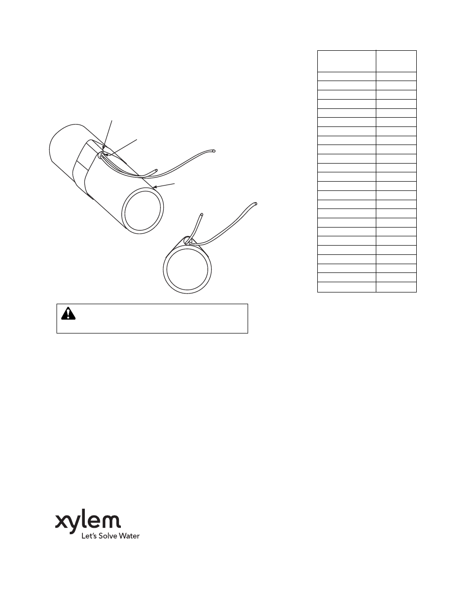
INSTALLING SENSOR
•
Strap the cylindrical sensor to the pipe as shown in Fig. 1.
• Wrap the pipe and sensor assembly with insulating tape to
insure adequate heat transfer to the sensor.
• See the wiring instruction sections of the NRF-VS or VS
Control instruction manuals for specific wiring instructions
to the controller. Do not exceed the water temperature
values listed in the temperature sensor chart.
INSULATING TAPE
TEMPERATURE
SENSOR
PIPE
FIG. 1
TEMPERATURE
Value
(in Degrees ºF)
(in 0hms)
30
17264
35
14985
40
13040
45
11374
50
9944
55
8714
60
7653
70
5941
80
4649
90
3667
100
2914
110
2332
120
1879
130
1524
140
1243
150
1021
160
842
170
699
180
583
190
489
200
412
210
349
220
297
230
253
TEMPERA
TURE
SENSOR CHART
WARNING:
Do not apply power to the sensor wires.
Failure to follow these instructions could result in
serious personal injury, death and/or property damage.
Xylem Inc.
8200 N. Austin Avenue
Morton Grove, Illinois 60053
Phone: (847) 966-3700
Fax: (847) 965-8379
www.xyleminc.com/brands/bellgossett
Bell & Gossett is a trademark of Xylem Inc. or one of its subsidiaries.
© 2012 Xylem Inc. P86273B May 2012