Bell & Gossett P82893D Series 60 In-Line Centrifugal Pumps User Manual
Page 29
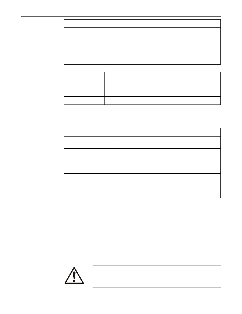
If your pump shaft...
Then...
Is keyed and uses a size 3J
coupler
Slide the coupler half on the shaft. Do not tighten the setscrew.
Is keyed and uses a size 4J
coupler
Slide the coupler half onto the shaft so that the shaft end extends 0.25 in.
(0.64 cm) past the coupler half flange face. Tighten the setscrews.
Is keyed and uses a size 5J
coupler
Slide the coupler half onto the shaft so that the shaft end is flush with the
coupler half flange face. Tighten the setscrews.
2. Position the coupler half on the motor shaft:
If...
Then...
The motor shaft contain a
dimple
Locate the coupler half on the shaft so that a coupler setscrew is positioned over
the dimple. Tighten the setscrew and make sure it seats in the dimple. Tighten
the other setscrew if there is one.
The motor shaft is keyed
Slide the coupler half onto the motor shaft. Do not tighten the setscrews.
3. Place the new insert in the pump side coupler half.
4. Lift the motor into position, align the insert and motor coupler half, and then bolt the
motor in place.
5. Slide the coupler over the insert:
If...
Then...
The motor and pump shafts both
contain a dimple
Proceed to the next step.
The motor shaft contains a
dimple and the pump shaft is
keyed
1. Use a screwdriver to slide the pump side coupler over the insert
as far as possible.
2. Gap the coupler by sliding the pump coupler half back 1/16 in.
3. Tighten the setscrews
The motor shaft is keyed and the
pump shaft is either dimpled or
keyed
1. Use a screwdriver to slide the motor side coupler over the insert
as far as possible.
2. Gap the coupler by sliding the motor coupler half back 1/16 in.
3. Tighten the setscrews
When an elastomeric type coupler is used with a keyed pump and/or motor shaft, do
not leave the insert compressed between the coupler halves. There must be a gap
between the ends of the insert and the coupler flanges to accommodate shaft
expansion and contraction. If the insert is not gapped, the pump and motor bearings
are subjected to excessive loads, which leads to premature failure. However, it is
possible to have too large a gap. The gap is considered excessive when the insert
teeth are not completely engaged in the coupler halves.
6. Insert the conduit and power leads on the conduit box.
7. Connect the power leads to the motor leads.
8. Install the conduit box cover.
9. Check that the motor rotation is clockwise when viewed from the back of the motor.
10. Fill and bleed the system and then check for leaks.
WARNING:
• Pressurize the pump body slowly while you check for leaks at all
joints with gaskets. Failure to follow these instructions can result in
serious personal injury or property damage.
Maintenance
Series 60 Installation, Operation, and Maintenance Manual
27